
2026-10-15
Why do vacuum brazed aluminium cold plates develop internal micro-leaks?
Micro-leaks in vacuum brazed aluminium cold plates usually trace back to filler flow, oxide condition or thermal stress at the braze joint. This technical note covers the checks, controls and test methods.
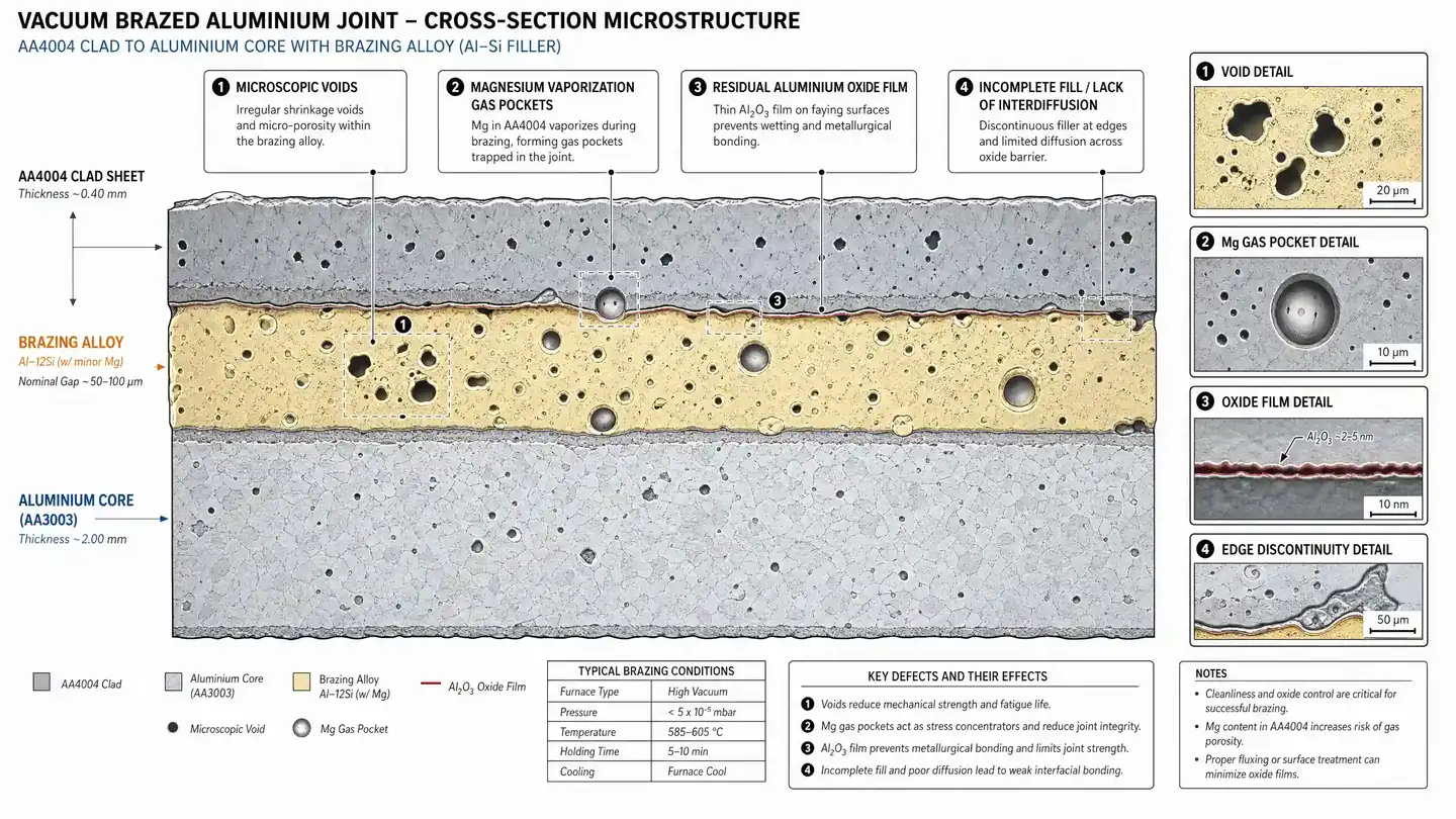
Figure 1: Metallurgical micro-leak mechanisms in vacuum brazed aluminium cold plates, including magnesium-related voids and interfacial oxide barriers.
Quick Answer: Internal micro-leaks in vacuum brazed aluminium cold plates are usually a braze-joint condition, not a single material failure. The first things to verify are the magnesium behaviour in the filler or clad system, the oxide condition before brazing, and the thermal/fixture condition during the braze cycle. Confirm the leak with helium mass spectrometry, then trace it back to the process record instead of replacing parts by guesswork.
A cold plate with an internal micro-leak has a path that connects two channels or connects a channel to atmosphere. That path can be too small for a pressure-decay test, so the inspection method has to match the leak-rate requirement before the cause can be evaluated.
Read the Leak Signature First
The leak test result is more useful when it is tied to the part condition. Record:
- Leak rate and repeatability, not only pass/fail
- Internal cross-channel leak or external leak
- Whether the leak appears only after thermal or pressure cycling
- Leak location from helium probing or sectioning
- Single-part issue or a shift across a production lot
A leak that appears only after thermal cycling usually points to a joint condition that opens under stress. A leak that is present immediately after brazing is more likely to be an incomplete joint, a void path or a mechanical damage point. A lot-wide change points to a material, cleaning or furnace condition rather than an isolated handling issue.
Three Process Areas to Check First
1. Magnesium in the Filler or Clad Layer
Magnesium is intentionally used in some aluminium brazing systems because it can disrupt the oxide film and getter oxygen in a vacuum furnace. The process risk is not simply the presence of magnesium; it is the combination of magnesium content, vacuum level, dew point, time at temperature and cooling rate.
If the vacuum or furnace profile is not matched to the filler, magnesium can vaporize or react before the filler has completed its flow. The result can be an incomplete joint, a local void or a path that opens later under thermal cycling. The correct check is the actual process record: filler lot and chemistry, vacuum leak-up rate, dew point, thermocouple data and the furnace profile used for that lot.
For magnesium-bearing 4xxx filler systems used in vacuum brazing, qualify the alloy and filler together. Do not transfer a furnace profile from one filler chemistry to another without a braze trial and cross-section.
2. Oxide Removal and Surface Condition
Aluminium oxide, Al2O3, forms quickly after cleaning and is not removed by vacuum alone. Cleaning must remove the existing oxide and leave a surface that will not re-oxidize before the parts enter the furnace.
The practical variables are the cleaning chemistry, bath concentration and temperature, rinse quality, drying time, storage time and handling. If the rinse conductivity or drying interval drifts, the braze can show local unbonded areas even when the furnace cycle looks correct. A braze trial with cross-sectioning is more useful than a visual inspection of the assembled part.
3. Fixture Condition and Thermal Gradient
Large, thin cold plates can develop significant temperature differences during heating and cooling. If the fixture does not support the part correctly, that gradient can produce distortion and shear stress at the braze interface. A void or oxide inclusion then becomes a crack initiation point.
Check the fixture contact pattern, thermocouple placement, heating and cooling rates, soak time and load position. A process that works for a small prototype may not produce the same thermal profile on a full-size production load. Thermal-cycle testing should follow the service condition, not a shortened bench cycle.
Other Failure Paths
Other conditions can produce the same symptom and should be excluded before changing the braze cycle:
- Insufficient filler coverage or incorrect joint clearance
- Oil, dust or machining residue left in the joint
- Voids from trapped gas or volatiles
- Corrosion in an incompatible coolant loop
- Mechanical damage after brazing
- A leak at a fitting, port or welded connection rather than in the core
This is why the inspection should include the complete assembly, not only the brazed core.
Failure Mode Check
| Observation | Likely mechanism | What to check | Corrective direction |
|---|---|---|---|
| Void visible in section, no leak at first | Filler-flow or magnesium-related process condition | Filler chemistry, vacuum, dew point, furnace profile | Re-qualify the braze cycle and section the trial |
| Unbonded area with oxide inclusion | Incomplete cleaning or re-oxidation | Bath control, rinse conductivity, drying and storage | Revise cleaning and handling; validate with a braze trial |
| Leak appears after thermal cycling | Residual stress or thermal-gradient effect | Fixture, thermocouples, heating/cooling rate | Revise fixture and profile; repeat cycle testing |
| Leak at a fitting or port | Connection damage or local braze condition | Joint design, torque, braze coverage | Rework the connection and retest |
| Leak rate rises across a lot | Material, cleaning or furnace drift | Lot traceability, furnace survey, process logs | Contain the lot and audit the process |
Inspection Sequence
- Define the acceptance requirement first: leak rate, tracer gas, test method, calibration and part volume.
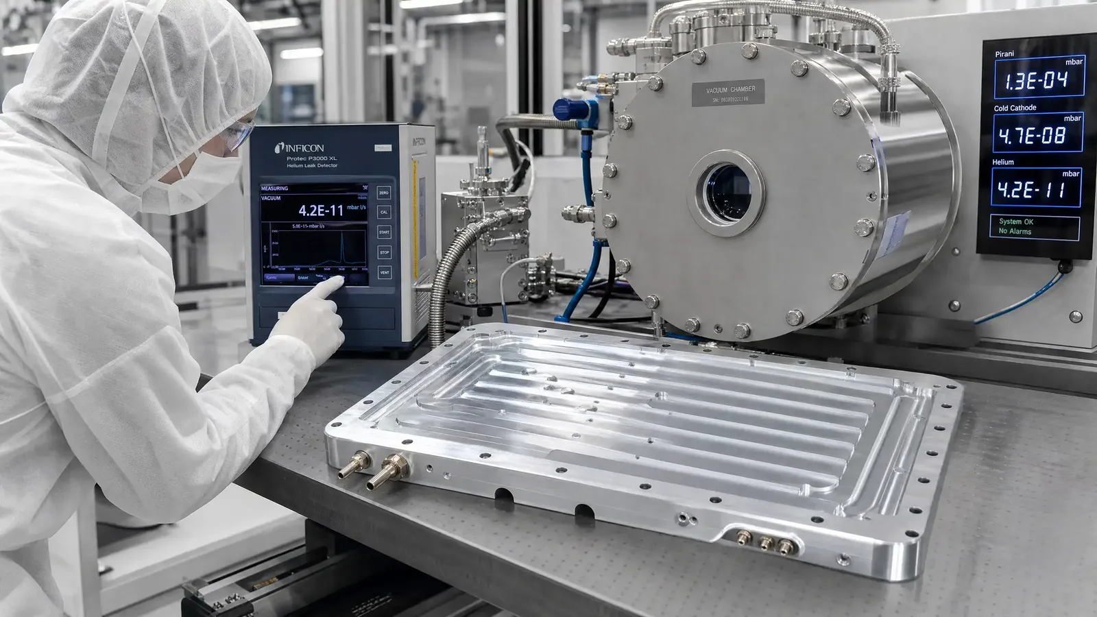
- Use helium mass spectrometry to confirm tightness and localise the leak path.
- Use ultrasonic C-scan only where the geometry and acoustic path allow it; it does not replace the helium test.
- Section a representative part to inspect filler flow, oxide films and void shape.
- Run pressure-cycle and thermal-cycle tests that represent the service condition.
- Compare the result with the process record for the same lot.
Production Controls That Matter
The controls that reduce micro-leak risk are process controls, not inspection alone:
- Material and filler lot control, including chemistry and traceability
- Cleaning bath, rinse conductivity, drying and maximum storage time
- Vacuum leak-up rate, dew point and furnace profile per alloy and filler
- Fixture contact, thermocouple placement and load position
- Filler weight and placement, joint clearance and assembly cleanliness
- Helium leak test method, calibration and acceptance criterion
- C-scan or section sampling where the design allows it
- Thermal-cycle and pressure-cycle validation before release
- Coolant chemistry, filtration and maintenance requirements
A high leak-test rejection rate usually points to a process drift. Sorting parts without correcting the process will move the problem to the next lot.
Specify the Leak Rate Correctly
A leak rate without the test method is not a useful specification. State the helium concentration, test pressure or vacuum, calibration method, part volume and acceptance criterion together.
High-reliability liquid-cooling and semiconductor cold plates may specify a helium leak rate around 1 x 10⁻⁹ mbar-L/s or lower. General industrial cooling equipment may use a different limit. The value must match the application and be verified with a qualified test procedure; it should not be presented as a universal guarantee.
Custom OEM and ODM Cold Plates
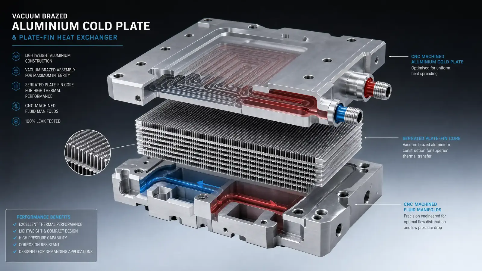
For custom design and OEM ODM cold plate projects, qualify the braze procedure on the same alloy, filler and joint style that will be used in production. A generic process approval is not enough when the cold plate has a different channel geometry, fitting design or thermal mass.
The aluminium radiator and plate-fin structures in this range are reviewed together with the thermal calculation and the braze process. For related engineering methods, refer to the plate-fin heat exchanger surface area calculation and the vacuum brazing vs CAB comparison.
Our team supports custom OEM oil cooler and OEM/ODM service projects for liquid-cooling plates, aluminium radiators and plate-fin heat exchangers. Send the alloy, filler, coolant, pressure, leak-rate and thermal-cycle requirements so the braze process and inspection plan can be reviewed together.
FAQ
Why do vacuum brazed aluminium cold plates develop internal micro-leaks?
Internal micro-leaks can come from incomplete filler flow caused by magnesium-related process effects, residual surface oxide, contamination, poor fit-up, an unsuitable furnace profile or thermal stress at the braze interface. The risk increases when the process window and inspection plan are not matched to the alloy and cold plate geometry.
Can helium mass spectrometer testing find leaks that pressure testing misses?
Helium mass spectrometer testing is generally more sensitive than a simple pressure-decay test because it uses a tracer gas and a calibrated detector. It can find smaller leaks, but the detection limit and acceptance criterion depend on the test method, chamber, part size, calibration and the specified leak-rate target.
What leak rate should be specified for a brazed cold plate?
The leak-rate target must match the application. High-reliability liquid-cooling and semiconductor applications may specify a helium leak rate around 1 x 10⁻⁹ mbar-L/s or lower, while other industrial systems may use a different criterion. The final value must be agreed between the customer and supplier and verified with a qualified test procedure.
What is the role of magnesium in vacuum brazing?
Magnesium can improve wetting and act as an oxygen getter in some aluminium brazing systems, but too much magnesium or an unsuitable vacuum/furnace cycle can cause vaporization, filler-flow disturbance and voids. The alloy, filler and vacuum profile must be qualified together.
How can OEM ODM cold plate projects reduce micro-leak risk?
Define the alloy and filler, control cleaning and surface preparation, qualify the vacuum and furnace profile, control fixturing and thermal gradients, use helium leak testing and other agreed inspection methods, and document material and process traceability for each production lot.
Need Help with a Cold Plate Micro-Leak Review?
Send the cold plate drawing, alloy and filler details, coolant, working pressure, leak-rate target, thermal-cycle requirement and inspection standard. Our engineers will review the braze process, fixture, inspection plan and production route before confirming the next step.
Request a Cold Plate Micro-Leak and Braze Review
Need Help Selecting an Oil Cooler?
Send us your specs or drawings and our engineers will size the right cooler for you within 24 hours.
Get a Free Quote Chat on WhatsApp