
2026-09-27
How to Calculate and Size a Bar and Plate Oil Cooler for Industrial Hydraulic Systems?
Learn how to calculate and size a bar and plate oil cooler for industrial hydraulic systems using heat load, LMTD, U-value, required area and a 15-20% safety margin.
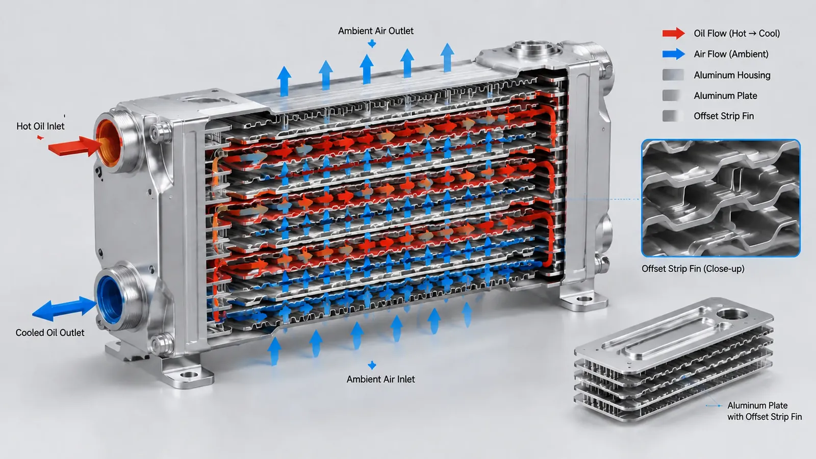
Figure 1: Internal structure and cross-flow heat transfer mechanism of an aluminum bar and plate oil cooler.
Quick Answer: To size a bar and plate oil cooler for an industrial hydraulic system, calculate the heat load first, determine the counterflow LMTD from the oil and air temperatures, apply the appropriate cross-flow correction factor F, select a U-value that uses the same reference area as A, and calculate the required area with
A = (Q x 1000) / (U x Delta T_m). Apply a 15% to 20% safety margin for fouling and severe ambient conditions, then confirm the final selection with the supplier's airflow and pressure-drop performance curves.
Sizing a bar and plate oil cooler for an industrial hydraulic system is not a matter of matching the pipe size or copying the dimensions of the original cooler. The heat exchanger must reject the actual hydraulic heat load while maintaining acceptable oil temperature, pressure drop and fan power across the full duty cycle.
A reliable calculation combines the hydraulic heat load, the log mean temperature difference, the overall heat transfer coefficient and the available cooling airflow. This guide explains the five-step engineering method and the information needed to turn a preliminary area calculation into a practical bar and plate hydraulic oil cooler selection.
What Information Is Needed Before Sizing?
Start with the operating conditions rather than a catalog size. The minimum data set should include:
| Input | Typical Unit | Why It Matters |
|---|---|---|
| Hydraulic motor or system power | kW | Gives a first estimate of heat rejection |
| Oil mass or volume flow | kg/s or L/min | Convert volume flow to mass flow before using the Q formula; determines oil-side velocity and heat transport |
| Oil inlet temperature | °C | Sets the hot-side temperature entering the cooler |
| Required oil outlet temperature | °C | Defines the cooling duty and viscosity target |
| Cooling-air inlet temperature | °C | Establishes the available temperature difference |
| Cooling-air outlet temperature | °C | Required for the LMTD calculation |
| Oil specific heat | kJ/kg·°C | Usually approximately 1.9 to 2.2 for mineral hydraulic oil |
| Allowable oil pressure drop | bar or kPa | Protects system efficiency and pump performance |
| Oil viscosity grade | ISO VG | Affects flow, heat transfer and pressure drop |
| Ambient contamination | dust, oil mist, humidity | Determines fouling margin and cleaning access |
If the system has a variable duty cycle, use the maximum sustained heat load rather than a short peak. A cooler selected only for average load can exceed the oil-temperature limit during the most demanding part of the cycle.
5-Step Bar and Plate Oil Cooler Sizing Calculation
The sizing method follows five steps: heat load, corrected LMTD, U-value, required area and safety margin. The calculation provides a preliminary thermal area; the final product must still be checked against fan airflow, oil viscosity, pressure drop and installation limits.
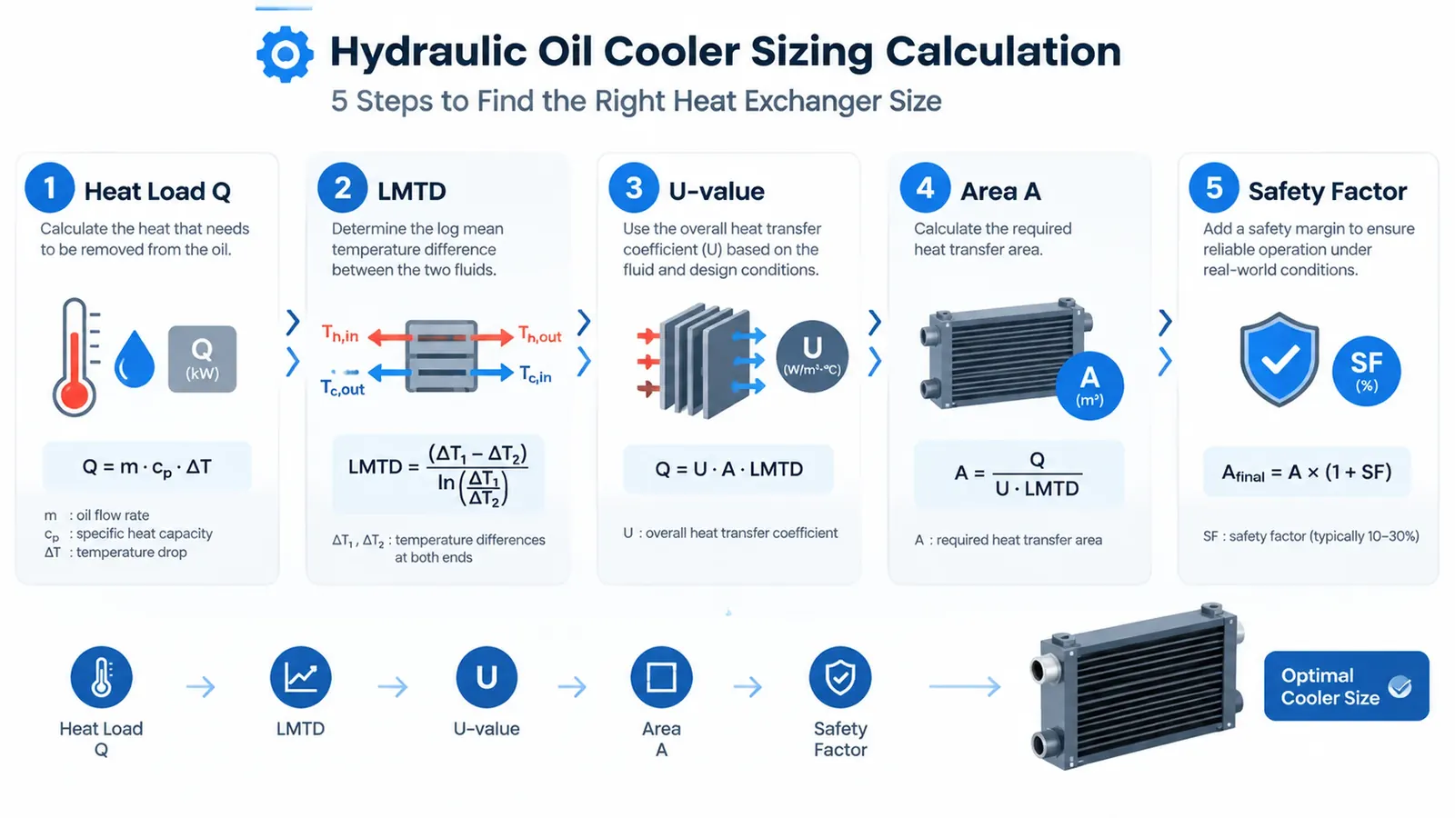
Step 1: Calculate the Heat Load (Q)
The direct heat load equation is:
Q = m × Cp × ΔT
Where:
Q= heat load in kWm= oil mass flow in kg/sCp= oil specific heat in kJ/kg·°CΔT= oil inlet temperature minus oil outlet temperature in °C- If the available flow is in L/min, first convert it to mass flow:
m = ρ × V_dot / 60,000, whereρis oil density in kg/m³ andV_dotis volume flow in L/min
Use the oil supplier's density and specific-heat data when available because these properties vary with fluid type and temperature.
For a preliminary estimate, industrial hydraulic systems often reject approximately 25% to 30% of input motor power as heat. For example, a 75 kW hydraulic power unit may require a preliminary heat-rejection estimate of roughly 19 to 23 kW, depending on the duty cycle and system losses.
Step 2: Determine the Log Mean Temperature Difference (LMTD)
For counterflow operation:
LMTD_cf = (ΔT1 - ΔT2) / ln(ΔT1 / ΔT2)
Where:
ΔT1 = oil inlet temperature - air outlet temperatureΔT2 = oil outlet temperature - air inlet temperaturelnis the natural logarithm
This is the counterflow LMTD. For a cross-flow air-to-oil bar and plate cooler, the effective mean temperature difference is lower: ΔT_m = F × LMTD_cf, where F is the flow-arrangement correction factor.
Obtain F from the manufacturer's performance data or standard heat-exchanger charts. It is less than 1.0 for most cross-flow arrangements. Do not use the counterflow LMTD directly as the final effective temperature difference for a cross-flow core. When ΔT1 and ΔT2 are equal, use that common value as the LMTD.
Step 3: Select the Overall Heat Transfer Coefficient (U)
The overall heat transfer coefficient depends on the oil-side convection, metal conduction, air-side convection and fin efficiency. For an aluminum bar and plate oil-to-air heat exchanger, a preliminary range is commonly:
U = 30 to 80 W/m²·°C
Use a lower value when air velocity is low, oil viscosity is high, the core is fouled or the airflow distribution is poor. Use a higher value only when the design and operating conditions support it.
The numerical U and A must use the same reference surface area. A U-value quoted on air-side area cannot be combined with an oil-side area. Confirm the definition with the supplier before using the calculation.
| Parameter | Typical Value Range | Unit | Engineering Note |
|---|---|---|---|
| Hydraulic heat rejection (Q) | 25% – 30% of motor power | kW | Preliminary industrial estimate |
| Oil specific heat (Cp) | 1.8 – 2.1 | kJ/kg·°C | Typical mineral hydraulic oil; verify with fluid data sheet |
| Overall heat transfer coefficient (U) | 30 – 80 | W/m²·°C | Preliminary aluminum bar and plate, air-to-oil; use a consistent reference area |
| Safety and fouling margin | 15% – 20% | % | Mining and dusty construction duty |
| Oil-side pressure drop | Project-specific | bar or kPa | Confirm against the full system budget |
Step 4: Calculate the Required Heat Transfer Area (A)
Convert the heat load to watts and calculate the corrected area:
ΔT_m = F × LMTD_cf
A = (Q × 1000) / (U × ΔT_m)
Where:
A= required heat transfer area in m²Q= heat load in kW1000converts kW to WU= overall heat transfer coefficient in W/m²·°CΔT_m= effective mean temperature difference in °C after the cross-flow correctionF= flow-arrangement correction factor from the applicable heat-exchanger data
Worked example: Assume Q = 18 kW, oil inlet = 65°C, oil outlet = 50°C, air inlet = 25°C and air outlet = 45°C.
ΔT1 = 65 - 45 = 20°CΔT2 = 50 - 25 = 25°CLMTD_cf = (20 - 25) / ln(20 / 25) = 22.4°C- With U = 45 W/m²·°C:
A_cf = (18 × 1000) / (45 × 22.4) = 17.9 m²
This is the counterflow reference area, not the final cross-flow area. For a cross-flow air-to-oil core, the effective mean temperature difference is ΔT_m = F × 22.4°C. Because F is less than 1.0, the corrected area will be larger than 17.9 m². For illustration only, if the selected flow arrangement gives F = 0.90, then ΔT_m = 20.2°C and the corrected area is (18 × 1000) / (45 × 20.2) = 19.8 m². The actual F must come from the manufacturer's performance data or heat-exchanger charts.
A heat balance should also be checked for the assumed air outlet temperature: m_air × Cp_air × (air outlet - air inlet) ≈ Q. If the assumed air flow cannot absorb the heat load, the outlet temperature and resulting LMTD are not physically consistent.
Step 5: Add the Fouling and Safety Margin
Multiply the corrected area by 1.15 to 1.20:
A_required = A_corrected × 1.15 to 1.20
Using the illustrative corrected area above:
19.8 × 1.20 = 23.8 m²
The safety margin is applied to the corrected cross-flow area, not to the 17.9 m² counterflow reference area alone. Use the higher end of the range for mining, construction, dusty plants, high ambient temperatures or systems where the oil condition is difficult to control. The margin is not a substitute for maintenance; it provides reserve capacity as fouling develops between service intervals.
How to Check the Preliminary Result
The area calculation is only the first pass. Before approving a bar and plate hydraulic oil cooler, confirm:
- Oil-side pressure drop: Compare the calculated pressure drop with the hydraulic system limit.
- Fan airflow and static pressure: Verify that the fan can deliver the required cooling airflow through the selected core.
- Air-side temperature rise: Confirm that hot air cannot recirculate back into the cooler intake.
- Oil viscosity: Check the viscosity at the lowest and highest operating temperatures.
- Installation envelope: Confirm core dimensions, mounting points, port positions and service clearance.
- Contamination and cleaning: Select fin spacing and access based on the site dust and oil condition.
- Part-load performance: Review the control strategy and bypass arrangement, not only full-load operation.
For a complete product match, review our bar and plate oil cooler assembly, hydraulic oil cooler with fan and custom OEM oil cooler options.
What to Send for a Custom Sizing Review
A supplier can complete the thermal and mechanical selection faster when you provide:
- Hydraulic motor power and measured heat load
- Oil flow rate, pressure and allowable pressure drop
- Oil inlet and outlet temperature targets
- Ambient or cooling-air temperature
- Oil type and ISO viscosity grade
- Fan voltage, available power and airflow data
- Core envelope, mounting points and connection sizes
- Duty cycle, contamination level and cleaning access
- Quantity, destination and required delivery date
Send the data with a sketch or photo of the installation. The engineering review should return a preliminary thermal check, recommended core arrangement, fan selection, pressure-drop estimate and quotation basis.
FAQ
How do I calculate the heat load for a hydraulic oil cooler?
Use Q = m × Cp × ΔT when the oil mass flow, specific heat and temperature drop are known. For a preliminary industrial estimate, hydraulic heat rejection is often taken as 25% to 30% of the input motor power, then confirmed from the actual duty cycle.
What is LMTD in a bar and plate oil cooler calculation?
LMTD is the counterflow log mean temperature difference between the hot oil and cooling air. For cross-flow air-to-oil coolers, apply a correction factor F so the effective mean temperature difference is ΔT_m = F × LMTD; obtain F from the flow arrangement or manufacturer data before calculating area.
What U-value should I use for an aluminum bar and plate oil cooler?
For an air-to-oil aluminum bar and plate heat exchanger, a preliminary U-value range of 30 to 80 W/m²·°C is commonly used when U and A refer to the same surface area, such as air-side area. The correct value depends on air velocity, oil viscosity, fin geometry, flow arrangement and surface cleanliness.
What safety margin is recommended for hydraulic oil cooler sizing?
Apply a 15% to 20% margin for oil-side fouling, air-side dust and high ambient conditions. Mining, construction, dusty environments and high-altitude sites may require additional review based on the actual cooling-air temperature and maintenance interval.
What information should I provide to an oil cooler manufacturer?
Provide the hydraulic system pressure and flow, heat load or motor power, oil inlet and outlet temperatures, ambient or cooling-air temperature, oil viscosity grade, allowable pressure drop, fan supply, mounting envelope and connection sizes.
Need an Engineering Sizing Review?
Send us the hydraulic flow, heat load, temperature targets, ambient condition and installation envelope. Our engineers will review the bar and plate oil cooler sizing calculation and recommend a practical core, fan and pressure-drop configuration.
Request a Bar and Plate Oil Cooler Sizing Review
Need Help Selecting an Oil Cooler?
Send us your specs or drawings and our engineers will size the right cooler for you within 24 hours.
Get a Free Quote Chat on WhatsApp