
2026-10-13
How to Calculate the Required Surface Area for a Custom Plate-Fin Heat Exchanger?
Learn how to calculate the required surface area of a custom plate-fin heat exchanger using heat duty, LMTD, the correction factor F, U-value and fin efficiency.
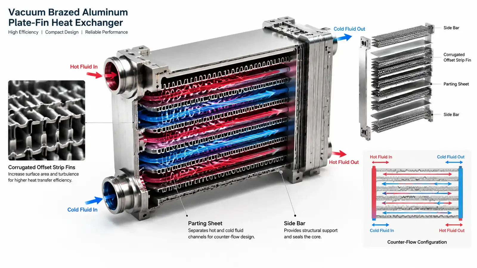
Figure 1: Internal matrix geometry of a vacuum-brazed plate-fin heat exchanger with typical 800–1500 m²/m³ surface compactness.
Quick Answer: To calculate the required surface area for a custom plate-fin heat exchanger, first determine the heat duty (
Q) from the fluid energy balance, then calculate the counter-flow LMTD and apply the flow correction factorF. Estimate the overall heat transfer coefficientUwith fin efficiency and fouling resistance, and solveA = Q / (U × F × LMTD). The result is a thermal reference area; pressure drop, mechanical design, fouling margin and any ASME Section VIII Div. 1 requirements must be checked separately.
The required surface area of a custom plate-fin heat exchanger cannot be selected from core volume or connection size alone. The heat-transfer area must be matched to the actual heat duty, the available temperature difference and the overall thermal resistance of both fluid sides.
This guide follows the standard LMTD method in four engineering steps and explains where the calculation is often misapplied: using kW instead of watts, omitting the correction factor F, mixing air-side and oil-side reference areas, or treating the calculated area as a finished core design. The result should be a defensible starting point for a prototype or detailed thermal review.
What Is the Required Surface Area of a Plate-Fin Heat Exchanger?
The required surface area is the heat-transfer area needed to transfer the specified heat duty at the available mean temperature difference and overall heat transfer coefficient.
For a compact aluminum plate-fin core, the surface density is often in the range of 800 to 1500 m²/m³. This means a small core volume can contain a large heat-transfer area, but the actual area that participates in heat transfer also depends on fin efficiency, flow distribution and whether the fin surfaces remain clean.
The calculation must use one consistent reference area. If U is quoted on air-side area, then A must also be calculated on air-side area. Mixing an oil-side area with an air-side U value will produce a misleading result.
4-Step Calculation Procedure (LMTD Method)
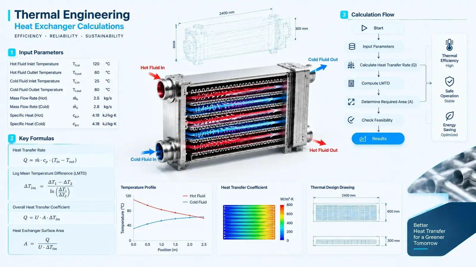
Step 1: Determine the Heat Duty (Q)
Calculate the heat duty from the energy balance on either fluid:
Q = m_dot × Cp × ΔT
Where:
Q= heat duty in Wm_dot= mass flow rate in kg/sCp= specific heat capacity in J/kg·KΔT= temperature change in K or °C
For a two-fluid heat exchanger, the hot-side and cold-side energy balances should agree:
Q_hot ≈ Q_cold
If they do not agree, check the flow measurements, fluid properties, phase condition and heat losses before using the value in the area calculation. If flow is given in L/min, convert it to mass flow before applying the equation.
Step 2: Calculate the Log Mean Temperature Difference (LMTD)
For counter-flow operation:
LMTD = (ΔT1 - ΔT2) / ln(ΔT1 / ΔT2)
Where:
ΔT1 = hot inlet temperature - cold outlet temperatureΔT2 = hot outlet temperature - cold inlet temperaturelnis the natural logarithm
For a cross-flow or multi-pass plate-fin core, apply a flow correction factor:
ΔT_m = F × LMTD
F is normally less than 1.0 and must come from the actual flow arrangement or the manufacturer's performance data. When ΔT1 and ΔT2 are equal, use that common value as the LMTD.
For multi-stream plate-fin exchangers, phase-change duty or strongly variable properties, the simple two-stream LMTD method may not be sufficient. Use a zone-by-zone calculation or the effectiveness-NTU method instead.
Step 3: Estimate the Overall Heat Transfer Coefficient (U)
The overall heat transfer coefficient combines the resistances on both fluid sides:
- Hot-side convection film coefficient
- Cold-side convection film coefficient
- Wall and braze conduction resistance
- Fouling resistance on each side
- Fin thermal efficiency (
η_f) - Flow maldistribution and bypass effects
A simplified resistance form is:
1 / U = 1 / h_hot + R_f,hot + R_wall + R_f,cold + 1 / h_cold
For finned surfaces, the fin efficiency and total surface efficiency must be included in the calculation. A fin with lower efficiency contributes less effective area than its geometric area suggests.
Typical surface compactness for aluminum plate-fin cores is approximately 800 to 1500 m²/m³, but compactness alone does not define U. The final U must reflect the actual fluids, flow rates, temperatures, fin geometry and cleanliness.
Step 4: Solve for the Required Surface Area (A)
Once Q, F, LMTD and U are known, calculate:
A = Q / (U × F × LMTD)
Where:
A= required heat-transfer area in m²Q= heat duty in WU= overall heat transfer coefficient in W/m²·KF= flow correction factorLMTD= counter-flow log mean temperature difference in K or °C
If Q is provided in kW, multiply by 1000 before using the equation. The result is a reference thermal area, not a final core drawing. Add the project fouling margin and confirm the selected fin geometry through the supplier's performance calculation.
Illustrative calculation: If Q = 15,000 W, U = 45 W/m²·K, F = 0.90 and LMTD = 20°C, then:
A = 15,000 / (45 × 0.90 × 20) = 18.5 m²
The values are illustrative only. The final U, F and LMTD must come from the actual fluid properties and flow arrangement.
Typical Parameters to Confirm Before Prototyping
| Parameter | Engineering Meaning | Verification Point |
|---|---|---|
Heat duty Q | Total heat transferred between fluids | Hot-side and cold-side energy balance |
| LMTD | Counter-flow mean temperature difference | Terminal temperatures and flow arrangement |
Correction factor F | Adjustment for cross-flow or multi-pass configuration | Supplier chart or thermal model |
Overall coefficient U | Combined thermal resistance | Film coefficients, wall, fouling and fin efficiency |
| Surface compactness | Heat-transfer area per core volume | Typically 800–1500 m²/m³ for compact plate-fin cores |
Required area A | Reference heat-transfer area | Same reference area as the quoted U |
| Fouling allowance | Reserve for deposits and contamination | Fluid condition, cleaning interval and maintenance plan |
| Pressure drop | Hydraulic or pneumatic penalty | Full-load flow and allowable system pressure loss |
| Mechanical design | Pressure and temperature boundary | Material, wall thickness, joints and test plan |
| Code scope | Applicable design and certification requirements | Confirm ASME Section VIII Div. 1 scope when required |
How to Check the Result Before Building a Prototype
A preliminary area calculation should be reviewed as part of the complete exchanger design:
- Check the energy balance: Confirm that hot-side and cold-side heat duties agree.
- Check
F: Confirm the flow arrangement and apply the correct correction factor. - Check the reference area: Make sure
UandAuse the same surface basis. - Check fin efficiency: Include fin efficiency in the surface effectiveness.
- Check fouling: Apply the project fouling resistance and maintenance assumptions.
- Check pressure drop: Confirm that the selected fin density is compatible with the allowable pressure drop.
- Check mechanical design: Review pressure, temperature, vibration, thermal expansion and connection loads.
- Check the code scope: Confirm whether ASME Section VIII Div. 1 or another standard applies to the pressure boundary.
For related engineering methods, review the bar and plate oil cooler sizing guide and the vacuum brazing vs CAB process comparison.
ASME Section VIII Div. 1 and Design Margin
If the project specification requires ASME Section VIII Div. 1, the pressure boundary, materials, design margins, inspection and documentation must be reviewed to that standard. The code scope is project-specific: not every plate-fin heat exchanger is automatically ASME-certified, and the certification route must be confirmed before the product is represented as compliant.
Fouling allowance is separate from mechanical code compliance. It should be selected from the fluid condition, cleaning method and expected service interval. Thermal margin and mechanical margin should both be documented, because an exchanger can pass a pressure test while still failing its thermal duty after fouling develops.
What to Send for a Custom Sizing Review
To support a custom thermal calculation, send:
- Hot-side and cold-side fluid names
- Mass flow or volume flow for each side
- Inlet and outlet temperatures
- Allowable pressure drop on each side
- Maximum working pressure and temperature
- Fluid properties at the operating point
- Expected fouling condition and cleaning interval
- Available core envelope, port sizes and mounting constraints
- Required code, documentation and certification scope
- Prototype or production quantity and delivery target
For custom design and OEM ODM production, include the required documentation scope with the same operating data. Our engineers can review the calculation and manufacturing route through the OEM/ODM service.
Our engineering team can review a custom OEM oil cooler, a bar and plate oil cooler assembly or a factory wholesale plate-fin program against the calculated duty and pressure-drop limits.
FAQ
How do I calculate the required surface area for a custom plate-fin heat exchanger?
Calculate the heat duty first, determine the counter-flow LMTD, apply the flow correction factor F, estimate the overall heat transfer coefficient U including fin efficiency and fouling, then solve A = Q / (U × F × LMTD). Keep Q in watts and confirm the reference area used for U matches the area calculated for A.
What is the formula for plate-fin heat exchanger surface area?
The working equation is A = Q / (U × F × LMTD). If Q is given in kW, convert it to watts before calculating A in square metres. The result is a thermal reference area and must still be checked against the selected fin geometry, airflow and pressure-drop limits.
How do I apply the LMTD correction factor F?
Calculate the counter-flow LMTD first, then apply F for the actual cross-flow or multi-pass arrangement. F is normally less than 1.0 and is obtained from heat-exchanger charts or the manufacturer's performance data. Do not use the uncorrected LMTD as the final effective temperature difference unless the configuration is truly counter-flow.
What surface compactness is typical for aluminum plate-fin heat exchangers?
Compact aluminum plate-fin cores commonly provide approximately 800 to 1500 m² of heat-transfer surface per cubic metre of core volume. The final compactness depends on fin height, fin pitch, fin type and the required pressure drop.
Does ASME Section VIII Div. 1 apply to every custom plate-fin heat exchanger?
Not automatically. ASME Section VIII Div. 1 can apply when the project specification, pressure boundary, jurisdiction or end user requires it. The applicable code scope, certification route and documentation must be confirmed for each project; do not describe the heat exchanger as ASME certified unless the certification scope has been verified.
Need Help with a Custom Plate-Fin Heat Exchanger Calculation?
Send the hot-side and cold-side duty, inlet and outlet temperatures, flow rates, pressure-drop limits and available envelope. Our engineers will review the LMTD calculation, fin geometry and manufacturing route before confirming the next design step.
Request a Plate-Fin Heat Exchanger Sizing Review
Need Help Selecting an Oil Cooler?
Send us your specs or drawings and our engineers will size the right cooler for you within 24 hours.
Get a Free Quote Chat on WhatsApp