
2026-11-04
Why does thermal shadowing degrade cooling in multi-fluid cooling stacks?
Thermal shadowing occurs when an upstream core raises the air temperature entering a downstream radiator. This engineering guide shows how to calculate the ITD loss, check the fan system and compare serial, side-by-side and split-V cooling layouts.
Quick answer: Thermal shadowing degrades cooling because heat rejected by an upstream core raises the air temperature entering the downstream core. With the downstream fluid inlet temperature unchanged, the smaller air-to-fluid temperature difference reduces heat transfer. In a heavily loaded serial stack, the loss can approach 40% of the downstream core's original initial temperature difference (ITD), but that figure must be calculated from the actual heat load and air mass flow. A larger fan alone cannot replace the missing temperature difference.
- The air is already warm. Ambient air may enter at 35°C, then leave an upstream charge-air cooler at 50–60°C before reaching the radiator.
- ITD falls first. Heat transfer depends on the difference between the fluid and the air entering the core, not on ambient temperature printed on a catalogue sheet.
- Fan load can change next. The heated air has lower density and a larger specific volume, so the complete system curve and fan operating point must be checked.
- The durable fix is an air-path change. Separate ambient intakes, side-by-side cores or a split-V arrangement can remove the downstream air preheating that a serial stack creates.
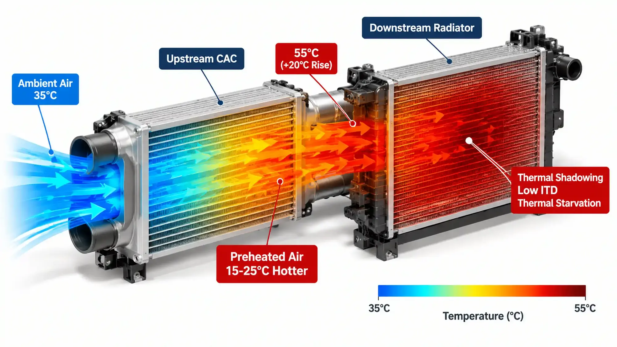
A downstream radiator sees air that has already done work
A multi-fluid cooling stack may contain a charge-air cooler, engine radiator, hydraulic oil cooler, transmission cooler or fuel cooler. When these cores share one air path, the first core does not simply remove its own heat. It changes the inlet condition for everything behind it.
In a typical charge-air cooler and radiator stack, ambient air crosses the CAC first. The CAC rejects heat to that air, so the air leaving the CAC is warmer than ambient. The engine radiator then receives this preheated stream. The outside temperature may still read 35°C, but the radiator inlet may be 50–60°C. A sensor mounted near the machine inlet will not show the thermal shadowing; a sensor placed at the radiator core face will.
This is a system-level effect, not a property of one core. It depends on the upstream heat load, air mass flow, the distance between cores, duct leakage and the amount of air that bypasses or recirculates around the stack. The same radiator can perform differently after a CAC is added, a fan is changed or an enclosure panel is moved.
The practical question is therefore not “what is the ambient rating?” It is “what air temperature reaches this core at full load, and what fluid temperature must be maintained at that inlet condition?”
Calculate the ITD loss before changing hardware
The first calculation is straightforward. For an air-cooled heat exchanger, initial temperature difference is normally defined as:
ITD = T_fluid,in - T_air,in
For an upstream core, the air-side heat balance is:
Q_upstream = m_dot_air x cp_air x Delta_T_air
Rearranged for the air temperature rise:
Delta_T_air = Q_upstream / (m_dot_air x cp_air)
The downstream core then sees:
T_air,down = T_ambient + Delta_T_air
ITD_down = T_fluid,in,down - T_air,down
The fractional loss relative to a clean, no-preheat baseline is:
ITD_loss = 1 - (ITD_down / ITD_baseline)
Use actual air mass flow, not nominal fan volume alone. Dry air has a specific heat near 1.005 kJ/(kg·K) at ordinary cooling-system temperatures; humid air and large temperature differences require a more detailed property calculation. For initial screening, this constant is usually adequate.
Worked example
Assume the following values for a screening calculation:
| Input | Example value |
|---|---|
| Ambient air entering the package | 35°C |
| Downstream fluid inlet temperature | 85°C |
| Baseline downstream ITD | 50 K |
| Upstream heat rejection | 84 kW |
| Air mass flow through the shared path | 4.2 kg/s |
| Air specific heat | 1.005 kJ/(kg·K) |
Calculate the upstream air temperature rise:
Delta_T_air = 84 / (4.2 x 1.005) = 19.9 K
The downstream core therefore receives air at about:
T_air,down = 35 + 19.9 = 54.9°C
Its new ITD is:
ITD_down = 85 - 54.9 = 30.1 K
The calculated ITD loss is:
ITD_loss = 1 - (30.1 / 50) = 39.8%
These values deliberately match the representative condition shown in Figure 1: 35°C ambient air, about 20 K of upstream preheat, a 55°C downstream air-on temperature and a low-margin 50 K baseline ITD. The resulting ITD falls to about 30.1 K, or 39.8%. That is the basis for the figure’s “up to 40%” label, not a universal fixed loss. Across the 15–25 K band shown in the diagram, the actual reduction still depends on upstream heat load, air mass flow and the downstream circuit’s baseline ITD. A lightly loaded core or a larger temperature margin may show a much smaller percentage loss; a circuit already close to its limit can become unstable after only a few kelvin of preheat.
If the downstream fluid temperature rises in service, the system does not remain at this first calculation point. The reduced heat transfer causes the fluid to run hotter until the heat balance closes at a less favorable temperature. That new equilibrium is the overheating condition the operator sees.
Why a bigger fan is not the first answer
Air density falls as temperature rises. The heated stream also has a larger specific volume, so the same mass flow occupies more volume in the downstream duct and plenum. Pressure loss through a restriction rises with velocity, and the fan curve itself shifts with inlet density. These effects have to be evaluated together.
A larger fan can increase mass flow, but it cannot make 50°C air behave like 35°C air. It may restore cooling by forcing more air through the core, at the cost of higher absorbed power, noise and discharge velocity. In some installations, a higher-volume fan also makes recirculation worse because hot air is thrown into a nearby wall or enclosure inlet.
Check the following before changing fan size:
- Actual fan speed and blade angle
- Motor current or measured shaft power against the fan curve
- Static pressure through the core, plenum, louvers and discharge stack
- Air-on temperature at each core face
- Leakage between the fan plenum and the ambient intake
- Wind direction and recirculation at the operating site
If the air path recirculates or bypasses a core, increasing fan power can move more of the wrong air. Seal the plenum, separate discharge from intake and verify the temperature distribution before ordering a larger fan.
For a single-circuit generator package, the same heat-balance logic is used in the 50°C generator radiator sizing method. The difference here is that two or more cores compete for the same air stream.
Serial, side-by-side and split-V layouts
There is no universal layout that suits every machine. The right choice depends on the available envelope, heat loads, service access and how much temperature rise the downstream core can tolerate.
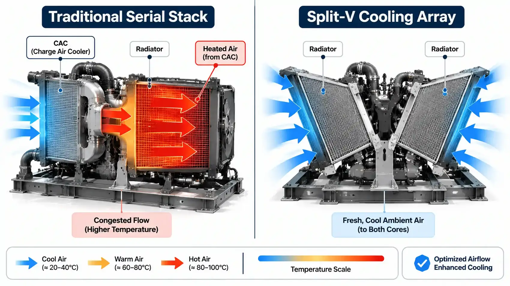
| Layout | Air-path behaviour | Advantages | Design penalties |
|---|---|---|---|
| Serial stack | Downstream core receives air heated by every upstream core | Compact, familiar, one main fan path | Thermal shadowing, cumulative pressure loss, difficult cleaning between cores |
| Side-by-side | Cores sit in parallel and receive ambient air through separate faces | More independent inlet temperatures; easier service access | Larger width or height; duct balance and fan sharing must be designed |
| Split-V array | Two angled banks receive air from separate directions | Can reduce stack height and downstream preheat | Larger envelope; airflow interference and wind sensitivity need checking |
| Remote or separated cores | Heat exchangers use different air paths or locations | Strong thermal separation | Longer hoses, structural support, pressure loss and installation cost |
A split-V layout is not automatically better. If the two banks discharge into the same enclosed space, or if the fan pulls air across one bank before it reaches the other, the same problem returns. The improvement comes from a genuinely independent intake path and a plenum that keeps hot discharge away from the inlet.
The layout choice should also consider maintenance. A core that is difficult to clean will gradually lose free area. In dusty service, a side-by-side arrangement may be more practical even when a serial stack would fit in a smaller package. For dust-related core design, see the open-pit mining radiator clogging guide.
How to diagnose thermal shadowing on site
A temperature complaint needs a measurement sequence, not a guess based on ambient temperature. Use a stable load and record the values at the same time.
- Map the air path. Mark the ambient intake, every core, the fan, the discharge and any openings that can bypass the intended path.
- Measure each core face. Take several readings across the air-on and air-off faces. Look for a hot band, a cold corner or a section shadowed by a bracket or duct.
- Check the air-side heat balance. Use upstream heat rejection and air mass flow to predict the temperature rise, then compare it with the measured rise.
- Recalculate the downstream ITD. Use the actual downstream fluid inlet temperature and the measured air-on temperature. Do not substitute the ambient temperature.
- Record the installed fan duty. Compare speed, power, static pressure and pressure differential with the density-corrected fan curve.
- Repeat at full thermal load. A stack can look acceptable at idle and fail after the engine, hydraulic system or compressor reaches working temperature.
The fluid-side heat rejection can be estimated from:
Q_fluid = m_dot_fluid x cp_fluid x Delta_T_fluid
A large disagreement between the fluid-side and air-side heat balances usually points to a flow measurement error, bypass air, sensor placement, fouling or an unaccounted heat source. Resolve that discrepancy before using the result to redesign the stack.
What to change first
The first corrective action depends on what the measurements show.
| Finding | First action |
|---|---|
| Small temperature rise and adequate ITD margin | Keep the existing layout, correct leaks and improve temperature monitoring |
| Large air-on temperature rise but stable fluid temperature | Improve plenum separation, reduce upstream heat load or evaluate a parallel-air layout |
| Fluid temperature rises only at high load | Check fan duty, core fouling and bypass air under the same full-load condition |
| Fan already at its power or noise limit | Avoid simply increasing speed; compare a larger fan curve with a layout change |
| Recurring dust blockage | Improve access and cleaning, then review fin pitch and face area |
| Limited footprint and high thermal load | Evaluate a split-V or remote-core arrangement with a full airflow study |
Do not use a fixed percentage for “thermal shadowing loss” in a quotation. The loss depends on the site and the load case. A design review should state the assumed upstream heat rejection, air mass flow, ambient condition and downstream allowable temperature, then show the resulting ITD.
For oil-side cores in the same package, review the bar-and-plate oil cooler sizing calculation and the bar-and-plate cooler assembly. The core can be thermally adequate on its own and still fail when its air-on condition is changed by another heat exchanger.
Design data to request from a cooling-stack supplier
A useful technical offer should include more than a core drawing. Ask for:
- Heat rejection for each fluid circuit at the design load and ambient condition
- Fluid flow, inlet temperature, allowable outlet temperature and pressure drop
- Air mass flow and the assumed air-on temperature at every core
- Core face area, fin pitch, fin type and net free area
- Fan curve corrected for site air density and system resistance
- Motor power, speed, insulation and drive arrangement
- Duct, louver, filter and discharge pressure losses
- Recirculation assessment and required separation from walls or hot discharges
- Structural support, thermal expansion and vibration isolation
- Service access for cleaning, fan removal and leak inspection
- Full-load acceptance readings for air, fluid and fan performance
If the stack is remote from the engine or generator, the fan arrangement also changes the air path. The induced draft versus forced draft comparison covers fan position, recirculation and installed power. Use it together with the cooling-stack heat balance rather than treating the fan as an isolated component.
FAQ
What does thermal shadowing mean in a cooling stack?
In this context, thermal shadowing means that an upstream heat exchanger has already warmed the air before it reaches a downstream core. The downstream core receives less cooling potential even when the outside ambient temperature has not changed.
Can thermal shadowing reduce downstream radiator ITD by 40 percent?
It can approach 40 percent in a heavily loaded serial stack when the upstream air temperature rise is large relative to the downstream core's baseline ITD. The value is not universal. Calculate it from the actual heat loads, air mass flow and fluid temperatures.
Does a larger fan always solve thermal shadowing?
No. A larger fan may restore mass flow, but it does not restore the missing air-to-fluid temperature difference. Increased fan speed can also raise noise, motor power and recirculation. Correct the air path before treating fan capacity as the only remedy.
Is a split-V cooling array always better than a serial stack?
No. A split-V layout can give each core a more independent ambient-air path, but it needs more envelope space and careful plenum separation. It is an option, not an automatic upgrade.
Where should temperatures be measured in a multi-fluid cooling stack?
Measure ambient air at the package inlet, air-on and air-off at each core face, fluid inlet and outlet for each circuit, and fan speed or pressure differential. Use several points across each face because a single probe can miss stratification and recirculation.
What data is needed for a cooling-stack design review?
Provide heat rejection for each fluid circuit, flow rates, allowable fluid temperatures, ambient and altitude, core dimensions, fan curves, duct and louver pressure loss, enclosure layout, dust conditions and full-load test data.
Need the cooling stack checked against the real heat balance?
Send the core arrangement, heat rejection for each circuit, measured air-on and air-off temperatures, fan curve and available envelope. Our engineers can check whether the downstream ITD is adequate before a new radiator, oil cooler or fan package is selected.