
2026-10-23
How to Design a 50°C High Ambient Radiator for a 2000kW Generator Set?
A 2000kW generator set at 50°C ambient needs a heat-balance-based radiator design, not a catalogue row count. This worked example covers heat load, air density, face area, fan pressure, ATB and test acceptance.
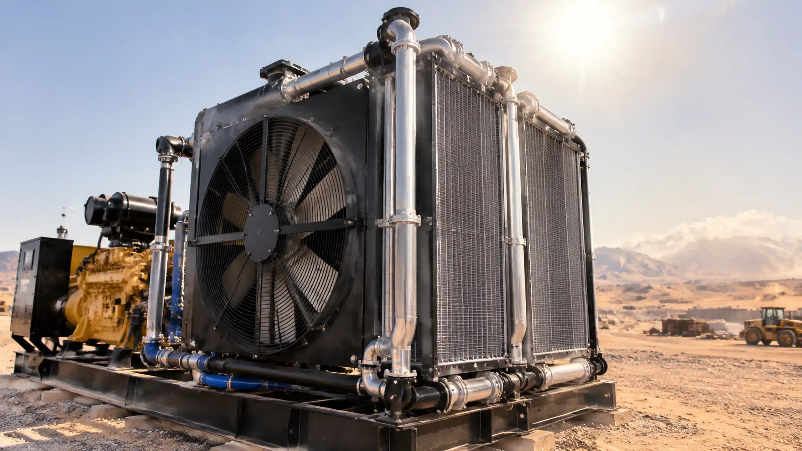
Quick engineering answer: A 2000kW generator set radiator at 50°C ambient should be sized from the engine OEM heat rejection at the site-rated load, not from a standard radiator table. Confirm the jacket-water and charge-air loads separately, calculate the required air mass flow at 50°C density, size the net face area and fan together, and prove the ATB margin against the installed enclosure and dust condition.
- Collect the real heat load. The electrical rating is not the heat rejected to the radiator. Use OEM data for jacket water and charge-air cooling at the required site rating.
- Calculate with hot-air density. At 50°C and sea level, dry-air density is about
1.09 kg/m³, compared with about1.18 kg/m³at 25°C. - Size the core and fan as one unit. A deeper core can add surface area while also increasing air-side resistance, fan power and cleaning difficulty.
- Validate ATB at full load. Treat 55–58°C ATB as a project target only when the engine OEM, coolant and site conditions support it.
Define ITD and ATB Correctly Before Sizing
Two temperature terms are often mixed up during a generator radiator review.
Initial temperature difference (ITD) is normally:
ITD = coolant inlet temperature - air inlet temperature
For a radiator receiving 90°C jacket water with 50°C air entering the core, the ITD is approximately 40 K. It is not 8–11 K. A figure in that range may refer to an air temperature rise, a terminal temperature difference, an approach value or another internal design parameter. Ask which two temperatures are being used.
Air-to-boil (ATB) is the ambient temperature at which the cooling system reaches its specified limit at a defined load, coolant and pressure-cap condition. It is a performance result, not a fixed margin added to the ambient temperature. A 55–58°C ATB target at 50°C ambient is possible for some projects, but it represents only 5–8 K of reserve and must be demonstrated by the selected engine, radiator, fan and installation.
The broader generator radiator sizing method covers catalogue derating and core-depth trade-offs. The next step is to apply those principles to a defined 2000kW package.
Inputs That Matter More Than Radiator Row Count
A 2000kW generator set can use different engine platforms, fan drives, enclosures and cooling circuits. No row count can replace a heat balance. Collect at least the following data before selecting a core:
| Design input | What must be confirmed |
|---|---|
| Site rating | Prime or standby power, electrical load profile and any altitude or ambient derating required by the engine OEM |
| Jacket-water heat rejection | Heat to the jacket-water circuit at the site-rated load, including whether oil-cooler heat is already included |
| Charge-air heat rejection | Heat to the separate CAC circuit, if fitted, and its coolant flow and maximum inlet temperature |
| Coolant conditions | Flow, inlet and outlet temperature, glycol concentration, pressure-cap setting and alarm limits |
| Air condition | Maximum 50°C inlet temperature, site barometric pressure, humidity, dust concentration and recirculation risk |
| Installation | Enclosure openings, radiator orientation, fan type, available absorbed power, noise limit and service clearance |
| Acceptance point | Load steps, stabilization criteria, permitted temperature tolerance and required test documentation |
Do not add jacket-water and charge-air heat loads twice. If the lubricating-oil cooler is served by the jacket-water circuit, its heat may already be included in the engine OEM jacket-water figure. If it is separately cooled by air or a second circuit, confirm how that heat leaves the package.
Worked Airflow Check for a 2000kW Genset
The following is a sanity check, not a universal selection. Use the real engine OEM values for a project.
Assume a site-rated 2000kW prime-power generator set at sea level and 50°C ambient. For this example:
- Jacket-water heat rejection:
560 kW - Charge-air heat rejection:
340 kW - Total heat to the radiator:
900 kW - Design air temperature rise:
12 K - Air specific heat: approximately
1.005 kJ/(kg·K) - Air density at 50°C and sea-level pressure: approximately
1.092 kg/m³ - Net face velocity:
4.5 m/s - Installed total-pressure resistance:
450 Pa(illustrative) - Fan total efficiency:
0.50
First, calculate the required air mass flow:
m_dot = Q / (cp × ΔT_air)
m_dot = 900 / (1.005 × 12) = 74.6 kg/s
Convert mass flow to actual volumetric flow:
V_dot = m_dot / air density
V_dot = 74.6 / 1.092 = 68.3 m³/s
Estimate the net core face area:
A_face = V_dot / face velocity
A_face = 68.3 / 4.5 = 15.2 m²
After a 10% allowance for blocked fin area, dust and structural obstructions, the required net face area is approximately 16.7 m². This is the free-flow area through the core, not the outside width of the radiator frame.
The approximate fan air power is:
P_fan ≈ V_dot × Δp_total / η_fan
P_fan ≈ 68.3 × 450 / 0.50 = 61.5 kW
The fan curve, motor efficiency, drive losses, altitude and enclosure pressure losses still need to be checked. At 1500 m site altitude under a standard-atmosphere approximation, density at 50°C falls to roughly 0.91 kg/m³; the same mass flow needs about 81.8 m³/s of actual air and more than 18 m² of face area at the same face velocity. Use the actual site pressure rather than a generic altitude correction.
Design the Core Around Pressure Drop and Dust
The core must provide enough heat-transfer surface without creating an air-side restriction that the fan cannot overcome. Increasing core depth adds surface area, but it also changes pressure drop, weight, cleaning access and the effect of partial fin blockage.
For a dusty generator installation, compare:
- Louvered fins where higher dry-surface performance is needed and the cleaning regime can support them
- Flat or serrated fins where straight, cleanable passages are more important
- Fin pitch and core depth that keep dust bridging under control
- Separate jacket-water and CAC circuits with correct headers and seals
- Structural support that allows thermal expansion without loading the headers
A deep 6-row or 8-row core may be the result of the thermal calculation. It should not be the starting assumption. The same core can perform differently when the enclosure restricts airflow or when a sand-covered fin pack reduces the free area.
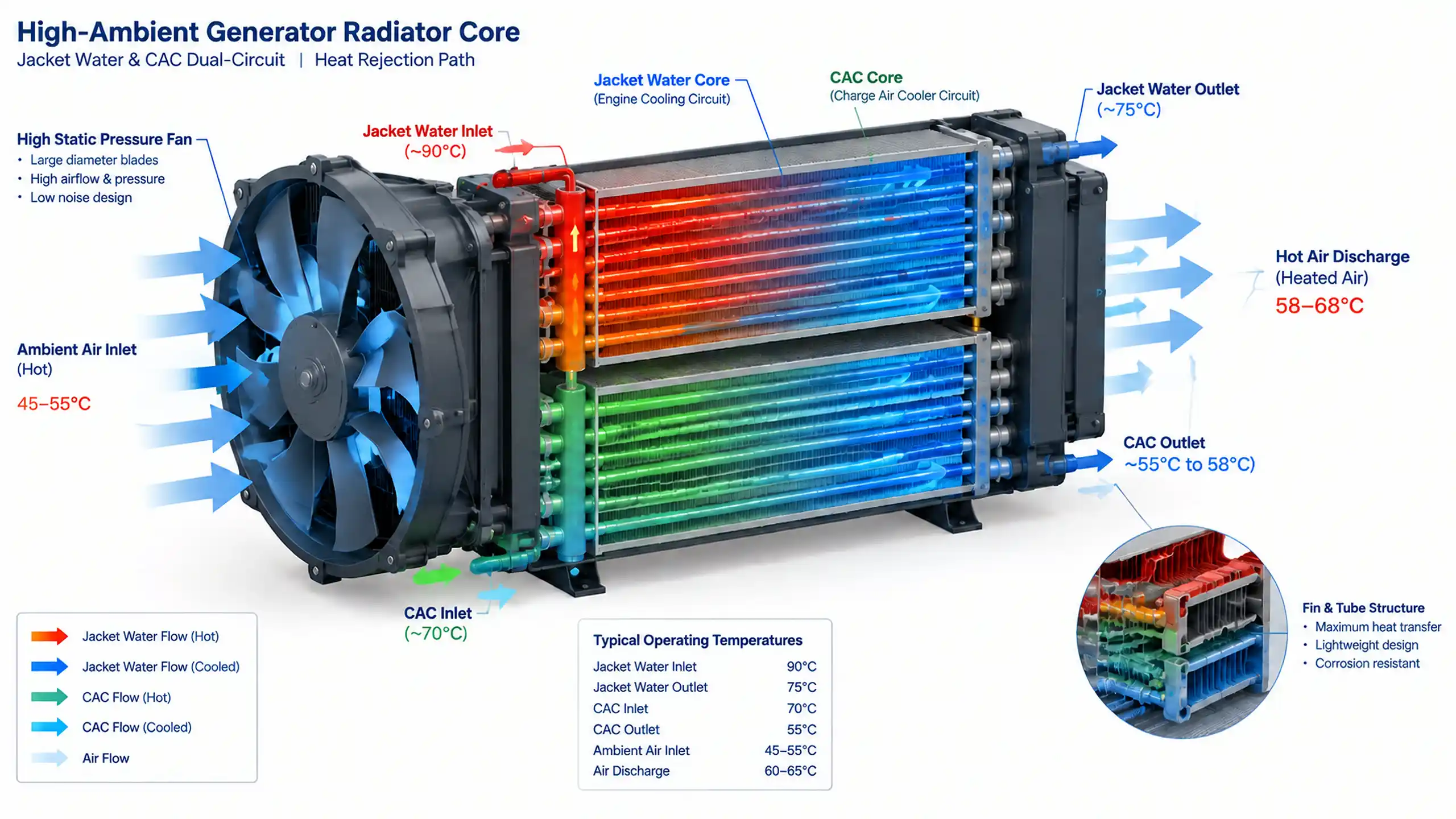
For custom core and pressure-boundary construction, review the vacuum brazing versus CAB comparison and the custom OEM heat-exchanger production route.
Check the Fan, Enclosure and Recirculation Together
A radiator that performs on an open test stand can fail inside a container or acoustic enclosure. Hot discharge air can return to the radiator inlet, especially when the package has a low roof, side louvers or a wind wall close to the fan outlet.
The review should include:
- Fan curve at the actual 50°C inlet density
- System resistance from the complete air path, not only the bare core
- Fan shroud clearance and blade-tip clearance
- Motor or belt-drive power at maximum fan speed
- Airflow distribution across the core face
- Separation of hot discharge air from enclosure inlet air
- Service access for core cleaning and fan inspection
- Noise treatment that does not create excessive pressure loss
A fan selected only by nominal airflow can be undersized for a thick, dust-loaded core. Conversely, simply increasing fan speed may exceed motor power, bearing limits, noise limits or belt capacity.
Coolant, Derating and ATB Protection
The radiator cannot compensate for an incorrect coolant specification or an unsuitable engine protection setting. Confirm glycol concentration, cap pressure, maximum top-tank temperature, low-coolant protection and the engine ECU derating strategy. Site altitude affects both air density and the coolant boiling point, so the 50°C ambient condition should be evaluated at the actual site elevation.
At full load, record:
- Ambient air temperature at the radiator inlet
- Core air-on and air-off temperatures
- Jacket-water inlet and outlet temperatures
- CAC coolant inlet and outlet temperatures
- Fan speed, absorbed power and pressure differential
- Engine load and any derating or alarm activity
- Stabilized temperatures after the agreed settling period
ATB should come from the selected cooling package performance, not from a generic sales statement. If the project requires 55–58°C ATB, make that a hold point in the technical offer and verify the calculation basis with the engine OEM.
What to Include in the Technical Offer
A useful 2000kW generator radiator offer should show more than a drawing and a price. It should state the assumed heat rejection, air inlet condition, site altitude, airflow, fan absorbed power, coolant circuit arrangement, core construction, pressure test and acceptance method. Any change to the enclosure, fan drive, coolant or engine rating can invalidate the original selection.
For an OEM or replacement project, send the engine model, generator package drawing, connection details, enclosure airflow path and site conditions through the OEM/ODM engineering service. Our engineers can review the heat balance and manufacturing route before a final design is frozen.
FAQ
What is the ITD of a radiator at 50°C ambient and 90°C coolant inlet?
ITD is the coolant inlet temperature minus the air inlet temperature. At 50°C ambient and 90°C coolant entering the radiator, the ITD is about 40 K. An 8–11 K value must describe a different temperature pair or calculation and should not be called ITD without clarification.
Is an 8-row core required for a 2000kW generator radiator at 50°C?
No universal row count applies. A deep 6-row or 8-row core may be needed to obtain enough surface area, but the correct choice depends on heat rejection, net face area, fin geometry, airflow, pressure drop, dust conditions and package space. Row count alone does not define performance.
Why does 50°C ambient air require a larger radiator and more fan work?
Hot air has lower density, so a given volumetric airflow carries less mass and absorbs less heat for the same temperature rise. The radiator needs the confirmed mass flow at 50°C, and the fan and motor must be checked against the actual air density and system resistance.
Is a 55–58°C ATB target sufficient for a 50°C site?
It can be a valid project target, but it is not a universal requirement. A 55–58°C ATB leaves only 5–8 K above the design ambient, so it must be supported by the engine OEM limit, coolant boiling point, cap setting, altitude, fouling allowance and validated full-load performance.
What data should be supplied for a 2000kW generator radiator quotation?
Provide prime and standby ratings, site ambient and altitude, engine OEM heat rejection for jacket water and charge air, coolant flow and temperatures, cap pressure, enclosure airflow path, available radiator envelope, fan drive, noise limit, dust condition and required acceptance documentation.
Need a 50°C Generator Radiator Review?
Send the engine model, site conditions, heat-rejection data, enclosure drawing and required load profile. Our engineers can review the airflow, core, fan and ATB assumptions before a 2000kW generator radiator package is quoted.
Request a 50°C Generator Radiator Design Review
Need Help Selecting an Oil Cooler?
Send us your specs or drawings and our engineers will size the right cooler for you within 24 hours.
Get a Free Quote Chat on WhatsApp