
2026-11-03
How to choose between induced draft vs forced draft for remote generator radiators?
The choice between induced draft and forced draft remote generator radiators depends on fan placement, air density, discharge velocity, recirculation risk, motor cooling and maintenance access. Compare the installed fan curve and site wind conditions rather than one generic efficiency number.
Quick answer: choose induced draft when the site benefits from a high, well-controlled vertical discharge and the fan motor can tolerate or be isolated from hot air. Choose forced draft when cool-air motor cooling, simpler maintenance access and direct core protection are more important than the discharge-plume trade-off. Confirm both options with an installed fan-curve comparison.
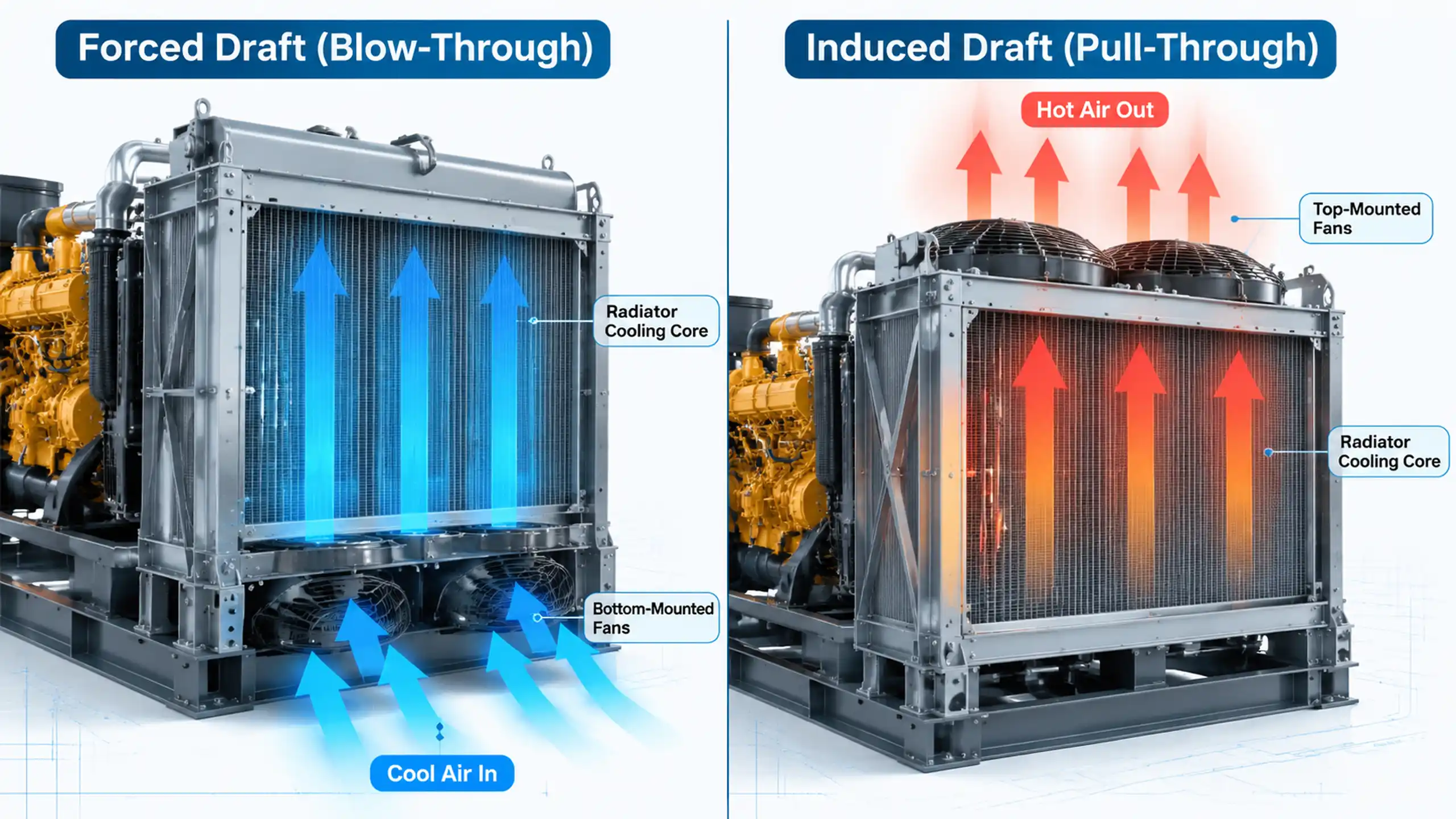
- Fan position: induced draft pulls air through the core; forced draft pushes air through it.
- Air density: the fan sees different temperatures in the two arrangements, so motor power and mass flow must be calculated at the actual fan location.
- Recirculation: a tall, high-velocity induced-draft plume can reduce hot-air return, but wind and nearby structures still matter.
- Maintenance: forced draft places the fan and motor in cooler ambient air; induced draft may need a high-temperature motor or external drive.
Compare the complete airflow path
A remote radiator is not selected by the fan alone. The system includes the core, plenum, ducting, louver, discharge stack, wind walls and the generator enclosure. A pressure loss added anywhere in that path changes the fan duty.
Record the static pressure through:
- Core and inlet filter or screen
- Inlet duct and turning vanes
- Fan inlet and outlet
- Discharge stack and rain hood
- Louvers and acoustic treatment
- Wind effects at the radiator outlet
Then compare the fan curve at the actual air density and speed. The two arrangements may use different fan diameters, tip speeds and motor positions, so a direct catalogue comparison without the installed system curve is not reliable.
Forced draft versus induced draft
| Feature | Forced draft / blow-through | Induced draft / pull-through |
|---|---|---|
| Fan location | Upstream, before the core | Downstream, after the core |
| Air through fan | Cooler ambient air | Hot air leaving the core |
| Motor cooling | Usually easier in the cool airstream | Requires high-temperature motor or external drive |
| Core face airflow | Depends on plenum and duct distribution | Often more uniform when the fan is centred downstream |
| Discharge plume | Lower velocity, more diffused | Can be designed for high vertical velocity |
| Recirculation | Needs wind screens or careful layout | Reduced risk with a properly designed plume, not eliminated |
| Maintenance | Fan and motor accessible on the cool side | Motor may be hotter and less accessible |
| Core weather exposure | Fan/plenum can provide some direct shielding | Core often faces the ambient intake and may need hail screens |
| Fan power | Must be calculated with cool dense air | Must be calculated with hot lower-density air and exit losses |
The source material's 8%–12% lower motor power for forced draft is not a universal rule. Cooler air is denser, and at the same volumetric flow and system resistance it can require more pressure and shaft power. Induced draft may reduce fan power because the fan handles hot lower-density air, but a high exit velocity and stack loss can offset that advantage. Compare power at the actual design point.
Recirculation and crosswind risk
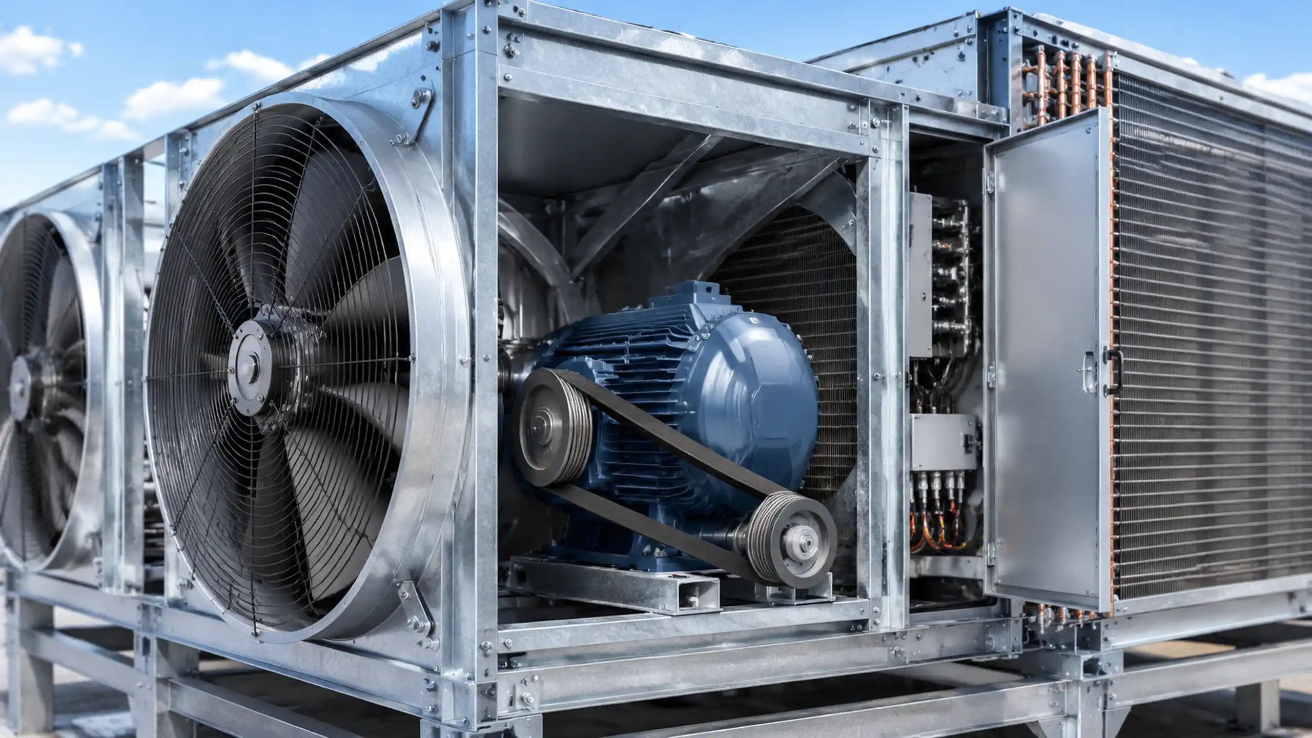
Hot-air recirculation occurs when discharge air returns to the radiator inlet. It raises the effective inlet temperature and can make a correctly sized core appear undersized. Recirculation depends on stack height, discharge velocity, wind direction, nearby walls and the distance to other equipment.
An induced-draft fan can produce a high-velocity vertical plume, which is often beneficial. However, a strong crosswind can bend the plume, and a nearby wall can still create a downwash or vortex. A forced-draft unit can also perform well when the outlet is designed with a stack, wind screen and adequate separation.
For critical sites, use CFD or a wind-tunnel study to check:
- Recirculation fraction at the inlet
- Discharge plume height and trajectory
- Wind speed and direction combinations
- Building wake and equipment obstructions
- Effect of partial radiator blockage
- Inlet temperature at the fan or core
Do not select induced draft solely to "eliminate" recirculation. Select it because the complete layout and fan duty make the plume more reliable.
Motor cooling and maintenance access
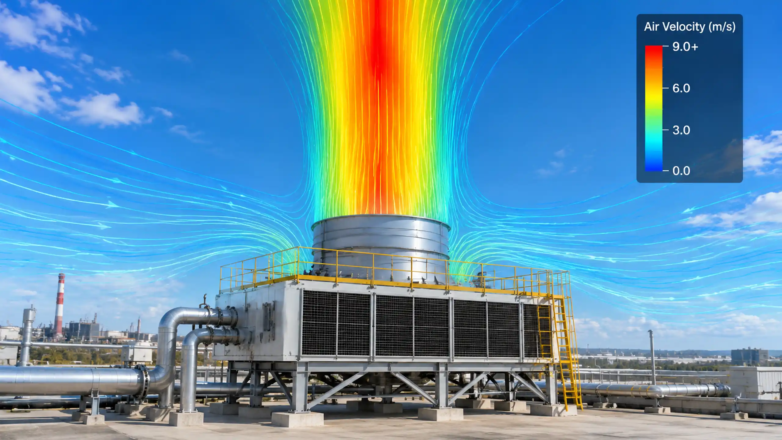
In a forced-draft arrangement, the fan and motor are normally on the cool inlet side. This can improve motor cooling and allow maintenance without opening a hot discharge plenum. The core is downstream, so the fan and plenum can also provide some protection from direct hail or debris, depending on the inlet design.
In an induced-draft arrangement, the fan is downstream and handles heated air. The motor may need:
- A high-temperature insulation class and bearing lubricant
- A motor located outside the hot duct
- A belt drive with the motor in ambient air
- Thermal protection and a verified cooling path
- A maintenance procedure that allows the fan to cool before access
High-temperature air does not automatically mean a motor will fail, but the motor nameplate and cooling method must be matched to the actual air temperature around the winding and bearings.
Fan power comparison
Use the fan power equation rather than a fixed savings claim:
fan air power ≈ actual volumetric flow × total pressure rise / fan efficiency
Compare the two arrangements at the same required core airflow and thermal duty. Include:
- Air density at the fan inlet
- Core and duct pressure drop
- Discharge velocity and exit loss
- Fan and drive efficiency
- Motor cooling and temperature derating
- Noise treatment and louver loss
An induced-draft fan handles warmer, lower-density air, which may reduce mass flow or pressure for a given fan speed. A forced-draft fan handles denser air, which can increase the pressure load for the same volumetric flow. The final motor power must come from the installed fan curve and the actual system resistance, not a generic 8%–12% assumption.
Selection matrix
| Project priority | Suggested starting point | Reason |
|---|---|---|
| Lowest risk of recirculation | Induced draft or forced draft with a well-designed stack and wind study | Fan arrangement alone does not guarantee a clean inlet |
| Easiest motor access and coolest motor air | Forced draft | Fan and motor can sit on the ambient side |
| Highest vertical discharge control | Induced draft | Downstream fan can be configured for a strong plume |
| Core protection from hail or debris | Forced draft with screens, or induced draft with a protected intake | Core exposure depends on the complete assembly |
| Lowest maintenance complexity | Forced draft in many layouts | Fan and motor are not buried in the hot plenum |
| Best use of available footprint | Case-specific | Duct length, stack height and service clearance decide |
There is no universal winner. The final choice should be supported by a heat balance, fan curve, recirculation review and maintenance plan.
Documentation to request
For either arrangement, request:
- Dimensioned assembly drawing
- Fan curve corrected for site air density
- Motor position, insulation class and cooling method
- Core face-velocity calculation
- Plenum and duct pressure-loss calculation
- Discharge velocity and stack height
- Recirculation study where required
- Hail screen, louver and filter details
- Maintenance access dimensions
- Pressure and leak test plan
- Noise data at the required distance
For the radiator heat balance, compare with the 50°C generator radiator sizing method. For a custom assembly, review the OEM/ODM engineering service and the industrial machinery cooling page.
Need help selecting the fan arrangement?
Send the generator heat rejection, site ambient and altitude, wind direction, radiator elevation, duct layout and required discharge height. Our engineers can compare induced and forced draft using the installed airflow path rather than a generic fan-power claim.
Request a Remote Radiator Design Review
Frequently Asked Questions
Which is better, induced draft or forced draft, for a remote generator radiator?
There is no universal winner. Induced draft often gives a stronger vertical discharge and more uniform core flow but places the fan in hot air. Forced draft keeps the fan in cooler ambient air and can improve motor access, but recirculation and core exposure must be reviewed.
Does forced draft always use 8–12% less fan power?
No. Fan power depends on actual volumetric flow, pressure rise, air density and efficiency. Cooler, denser air can increase the pressure and shaft power for the same volumetric flow, so the installed fan curve must be compared rather than applying a fixed percentage.
Does induced draft eliminate hot-air recirculation?
It can reduce recirculation when the discharge velocity and plume are correctly designed, but it does not eliminate recirculation in every wind and building layout. Stack height, nearby structures and wind direction still matter.
Which arrangement protects the core from hail?
The answer depends on the complete assembly. A forced draft fan and plenum can shield the core from direct hail, while an induced draft arrangement normally places the core on the ambient intake side. Screens, louvers and orientation must be reviewed for the actual site.
What data is needed to compare the two options?
Provide heat rejection, airflow, site altitude and ambient temperature, wind data, duct and plenum pressure loss, fan curves, acceptable noise, maintenance access, motor location and the required discharge height.