
2026-10-30
How to cross reference aftermarket coolers for Atlas Copco and Sullair compressors?
Cross-referencing an aftermarket compressor cooler requires more than a matching brand name. Confirm the part number, dual-circuit layout, dimensions, pressure ratings, port arrangement, pressure drop and installation envelope before ordering.
Quick answer: cross-referencing an aftermarket compressor cooler is a dimensional and performance check, not a brand-name lookup. Match the compressor model and original part number first, then verify the dual-circuit arrangement, pressure and temperature limits, port geometry, mounting envelope and allowable pressure drop.
- Part number and revision: the same compressor family can use different cooler assemblies by serial range or market.
- Physical fit: compare core dimensions, mounting centers, fan shroud, bracket position and every port.
- Circuit and pressure: confirm oil and air sections separately; do not assume a generic 16 bar or 25 bar rating.
- Performance: compare CFM, cooling conditions, outlet temperature, pressure drop and test requirements before approving the replacement.
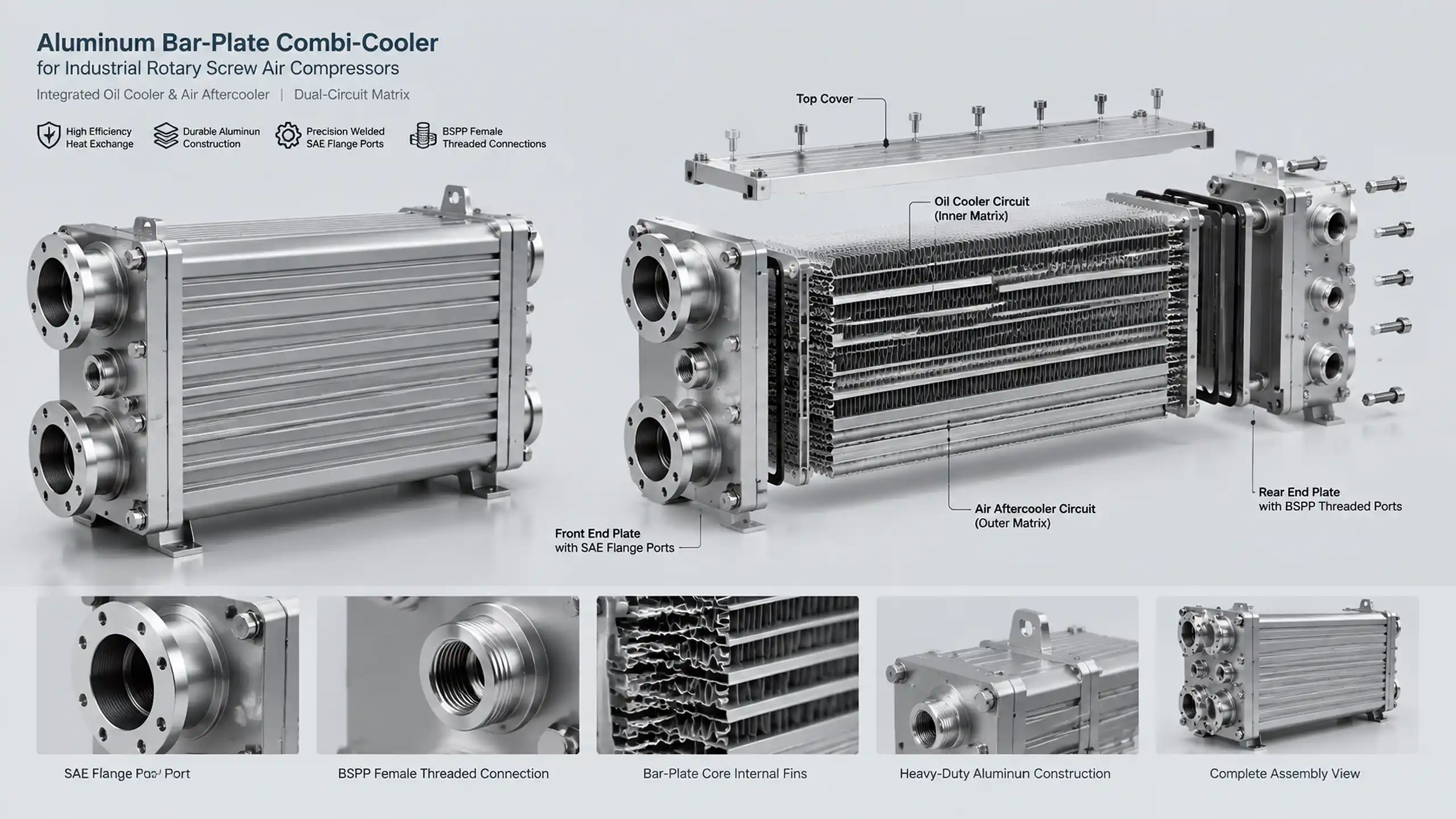
Start with the compressor identity, not the brand name
Atlas Copco and Sullair each use multiple compressor platforms, revisions and cooling arrangements. A cooler listed for one model family may not fit another machine with the same nominal power or footprint. The cross-reference should begin with:
- Compressor make and model
- Serial number or build range
- OEM cooler part number and revision
- Old cooler nameplate
- Photos of all four sides and the installed position
- Port dimensions and thread or flange type
- Fan, shroud and bracket arrangement
The OEM part number is the strongest starting point, but it still needs a drawing check. A seller may list a part as a match because it fits one revision, while a later compressor uses different port angles or an added separator connection.
Five-point aftermarket cooler cross-reference
| Check | What to compare | Failure risk if missed |
|---|---|---|
| Part number and revision | OEM code, compressor serial range and drawing revision | Wrong internal circuit or later-model mismatch |
| Dimensional envelope | Core size, depth, mounting centers, brackets and shroud | Installation interference or fan damage |
| Circuit arrangement | Separate oil and air passages, flow direction and separator connections | Poor cooling, cross-contamination or blocked service access |
| Pressure and temperature | Continuous, peak and proof pressure plus operating temperature | Leak, deformation or unsupported pressure claim |
| Ports and performance | SAE/BSPP connections, port angle, CFM and allowable pressure drop | Adapter stacks, low flow or excessive pressure loss |
This matrix is a screening tool. The final release should be based on a dimensioned drawing and a performance check against the compressor duty.
Verify the physical envelope on a drawing
A cooler can look similar from the front and still fail to install. Compare the following dimensions on a marked drawing:
- Core width, height and thickness
- Overall length including tanks and manifolds
- Mounting-hole spacing and bracket offset
- Distance from the mounting plane to the ports
- Port center positions and angles
- Fan diameter, blade clearance and shroud depth
- Service clearance for cleaning and hose removal
Do not rely on a catalogue photo for the final check. If a bracket or port is different, an adapter may appear to solve the installation while adding a restriction, a leak path or a fatigue point.
Confirm the oil and air circuits separately
A combi-cooler may contain an oil cooler and a compressed-air aftercooler in one assembly. The two circuits must remain separate, with the correct flow direction, port sizes and internal separation. Confirm whether the original unit has:
- One combined core or two separate heat-exchanger sections
- Oil-to-air and compressed-air-to-air circuits
- An integrated moisture separator or drain connection
- A thermostatic bypass or oil-flow control function
- Different pressure ratings for each circuit
- Specific inlet and outlet orientations
Do not connect the replacement by matching only the external pipe positions. Internal leakage between circuits or a reversed flow path may appear as a temperature problem rather than an obvious leak.
Verify pressure and temperature from the compressor data
The source material's 16 bar air-side test rating and 25 bar oil-circuit working pressure may describe a particular compressor family, but they are not universal values. The replacement must be checked against the actual compressor specification.
| Parameter to confirm | Why it matters |
|---|---|
| Continuous oil pressure | Defines the pressure boundary and joint design |
| Compressed-air working pressure | Sets the air-side pressure load |
| Peak pressure and duration | Can control fatigue and deformation |
| Proof or test pressure | Confirms the required inspection route |
| Oil and air temperature | Affects material strength, seals and thermal expansion |
| Pressure cycles | Determines whether fatigue qualification is needed |
| Safety and documentation scope | Must match the project and jurisdiction |
A supplier should be able to show the design basis for a replacement, not just state a maximum pressure in a sales table. If the old cooler has a higher rating than the proposed replacement, stop and obtain a documented engineering comparison.
Match ports without stacking adapters
Port geometry is part of the cross-reference, not an installation detail to solve later. Check:
- SAE flange size and bolt pattern
- BSPP or metric thread type
- Port angle and accessibility
- Tube diameter and wall thickness
- O-ring or gasket material
- Distance to the compressor body and service panel
- Hose routing and strain relief
An adapter can make a connection physically possible while increasing pressure drop, creating an unsupported cantilever or adding a leak path. If several adapters are needed, the replacement is probably not the correct form-fit unit.
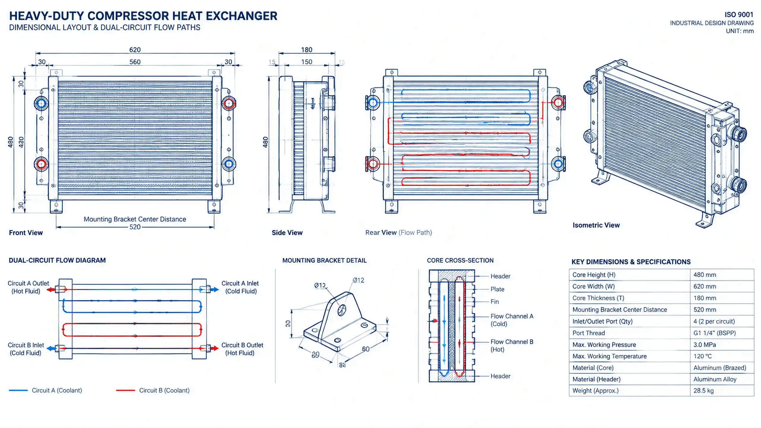
Compare pressure drop across the operating range
A single pressure-drop number at one flow point is not enough. The aftercooler or combi-cooler must remain within the compressor's allowable pressure drop across the required CFM range.
The source material mentions a target below 0.2 bar (3 psi) for one application. That may be a useful project criterion, but it is not a universal rule. Confirm the allowable pressure drop from the compressor OEM or the system design, then compare it at the actual flow, pressure and air density.
Review:
- Air-side pressure drop at minimum and maximum CFM
- Oil-side pressure drop at operating viscosity
- Cold-start pressure drop
- Pressure drop after dust or oil fouling
- Compressor discharge temperature and outlet temperature
- Cooling-air or cooling-water condition
- Fan power and airflow through the installed enclosure
A replacement with the correct external dimensions can still cause poor performance if its internal flow area, fin geometry or circuit arrangement is different.
Inspect construction and test requirements
The replacement should be reviewed for the same class of construction as the original application:
- Aluminum alloy and vacuum-brazed core where appropriate
- Correct filler metal and joint design for the pressure duty
- Reinforced headers, brackets and port connections
- Compatible seals and coatings
- Leak test, proof test and pressure-cycle requirements
- Cleanliness of the internal passages
- Protection for transport and storage
For high-pressure or high-cycle applications, ask for the test plan and traceability before approving the sample or production batch.
Validate the replacement before full production
A first-article inspection should compare the replacement with the original at the interface level and at the performance level.
| Validation item | Acceptance evidence |
|---|---|
| Compressor identity | Model, serial range and OEM part number agree |
| Overall dimensions | Drawing dimensions match the installation envelope |
| Mounting points | Brackets, isolators and hole centers fit without modification |
| Circuits | Oil and air paths are separate and flow in the correct direction |
| Ports | Thread or flange type, angle, size and sealing method match |
| Pressure | Continuous, peak and proof pressure meet the specification |
| Thermal duty | Outlet temperature meets the required condition at rated flow |
| Pressure drop | Within the compressor or system limit across the operating range |
| Leak and pressure test | Documented results meet the approved test plan |
| Installation check | No hose strain, fan interference or service-access problem |
After installation, record the compressor load, ambient or cooling-water temperature, inlet and outlet temperatures, pressure drop and fan condition. Compare those readings with the original or with the approved performance calculation. A replacement that fits but runs hotter or loads the compressor more heavily is not a successful cross-reference.
When an aftermarket replacement is not appropriate
Do not force a substitute when:
- The OEM part number cannot be confirmed
- The compressor uses a different circuit or control arrangement
- The required pressure or temperature exceeds the proposed cooler rating
- The replacement needs major bracket or pipe modification
- The allowable pressure drop cannot be demonstrated
- The application requires documentation or certification the supplier cannot provide
- The old unit failed because of a system problem that has not been corrected
In those cases, request a custom design based on the compressor data rather than choosing the closest catalogue size.
Information needed for an aftermarket cooler quotation
Send a complete cross-reference package:
- Compressor make, model and serial number
- OEM cooler part number and revision
- Photos of the installed cooler and nameplate
- Dimensional drawing or measured sketch
- Oil and air circuit layout
- Continuous, peak and test pressure
- Operating temperatures and allowable pressure drop
- Full-load CFM or compressor output
- Cooling-air or cooling-water conditions
- Connection type, size and orientation
- Required documentation, sample quantity and delivery target
Our engineers can review the replacement route through the OEM replacement air compressor aftercooler and oil cooler or the custom compressed-air cooler. For the broader compressor package, see the compressor and vacuum pump cooling solutions.
Brand names are used only to describe compatibility. TH is not affiliated with Atlas Copco, Sullair or their respective owners. Confirm the exact model and drawing before ordering.
FAQ
How do I cross-reference an aftermarket cooler for an Atlas Copco or Sullair compressor?
Start with the compressor model, serial number and OEM cooler part number, then compare dimensions, dual-circuit layout, pressure and temperature ratings, connection types, mounting points and allowable pressure drop. A brand name alone is not enough.
Are Atlas Copco and Sullair compressor coolers interchangeable?
Not generally. Some models or revisions may share a similar envelope, but the circuits, ports, brackets, pressure ratings and airflow arrangement can differ. Confirm the exact model and drawing before using an aftermarket replacement.
Is a 25 bar oil-circuit rating universal?
No. The required working, peak and proof pressures depend on the compressor, circuit and applicable specification. A 25 bar figure may apply to one project, but it must not be presented as a universal rating for every oil cooler.
Is an air pressure drop below 0.2 bar always required?
No. A 0.2 bar limit may be appropriate for a particular compressor and operating range, but the actual allowable pressure drop should come from the OEM specification or system calculation. Verify it across the required CFM range.
What information is needed for a replacement cooler quotation?
Provide the compressor model and serial number, OEM part number, photos, dimensioned drawing, circuit arrangement, required pressure and temperature, port details, ambient or cooling-water condition, allowable pressure drop and delivery quantity.
Need to Verify a Compressor Cooler Cross-Reference?
Send the compressor nameplate, old cooler photos, part number and dimensional drawing. Our engineers can check the envelope and circuit arrangement before confirming a replacement quotation.