
2026-11-02
Why do hydraulic rock breakers cause rapid fatigue failure in excavator oil coolers?
Hydraulic rock breakers can send high-frequency return-line pressure pulses into an excavator oil cooler. Measure the actual pressure waveform, return backpressure, accumulator condition and brazed-core fatigue margin before changing the cooler.
Quick answer: hydraulic rock breakers can cause rapid cooler fatigue because their return flow is not steady. Each breaker cycle creates a pressure pulse, and repeated pulses can fatigue the brazed joints of an excavator oil cooler even when the average return pressure looks acceptable.
- Measure the waveform, not only the average pressure. A gauge can show a normal return pressure while missing high-frequency peaks.
- Check the return path. Accumulator condition, filter restriction, hose size and fittings can amplify the pressure pulse.
- Check the core pressure envelope. Static burst pressure and fatigue life are different requirements.
- Fix the circuit before fitting a stronger cooler. A replacement installed into the same pulsation problem may fail again.
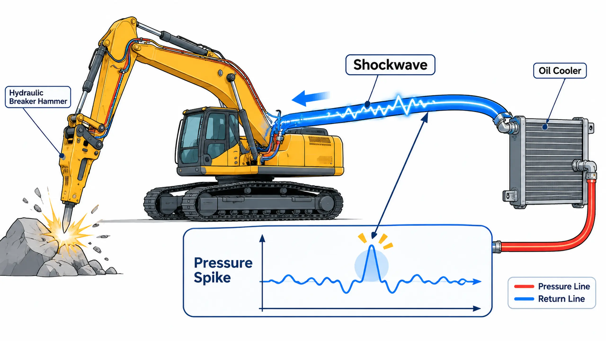
The return line is not a steady-flow pipe
A hydraulic breaker uses a reciprocating piston and rapidly switching valve. The return oil does not move at a perfectly constant rate. It accelerates and decelerates with every blow, and the connected hoses, fittings, filter and cooler respond to those changes.
When the breaker is mounted on an excavator, the return circuit may include:
- A dedicated breaker return line
- The machine's main return line
- A return filter and backpressure valve
- An accumulator or pulsation damper
- Quick couplers and long hose runs
- An oil cooler shared with other hydraulic functions
A cooler connected to that circuit receives a dynamic pressure profile. The average pressure may be low while the peak pressure is much higher. The peak and the number of cycles determine fatigue damage.
What the pressure pulse does to a bar-and-plate core
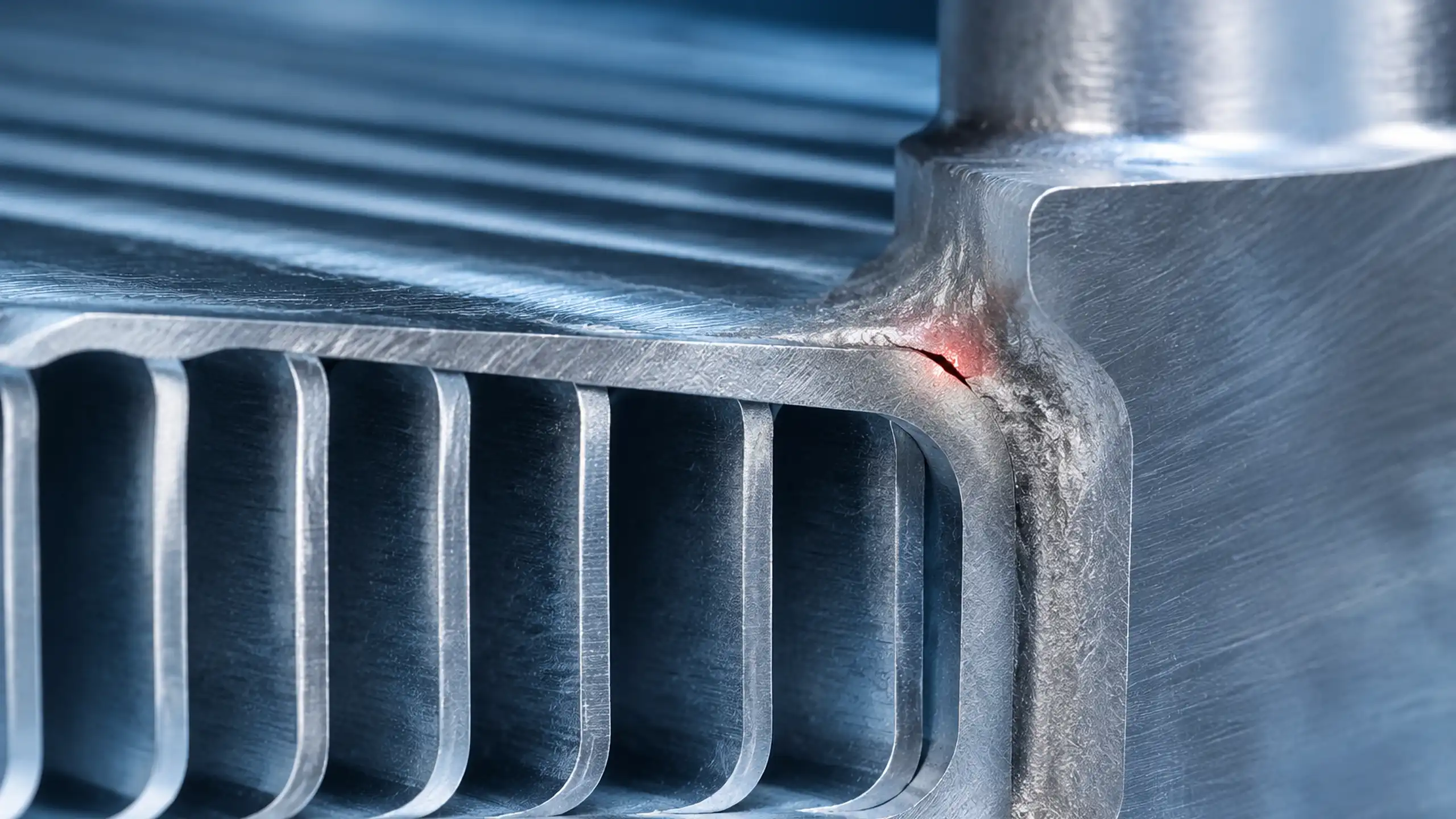
A bar-and-plate cooler has internal fins, parting sheets, bars and headers joined by brazing. The brazed fillets create local geometry changes where stress can concentrate. Repeated pressure pulses can initiate a crack at a fillet, at a header transition or at a mounting bracket.
The failure does not necessarily occur on the first pressure spike. It can develop as:
- A small crack at a braze fillet or joint edge
- A leak path through the core or header
- A visible deformation or rupture after repeated cycling
- Cross-contamination between oil and cooling fluid in a two-circuit cooler
This is why a static pressure test can pass before the cooler fails in service. The test does not reproduce the same pressure amplitude and cycle count.
Blow frequency and cooler cycles
Hydraulic breakers commonly operate in the range of hundreds of blows per minute, but the exact frequency depends on the breaker size, hydraulic flow and control mode. A value such as 300–600 blows per minute may be typical for one class of breaker, not a universal figure.
For fatigue review, record:
- Blows per minute at the actual working setting
- Pressure peak at the cooler inlet
- Pressure peak at the cooler outlet
- Pressure cycle range and mean pressure
- Time at each breaker setting
- Number of shifts and operating hours
- Accumulator precharge and condition
The cooler does not need to see the full pump pressure to be damaged. A pressure pulse travelling through the return line can create a local differential across the core and its connections.
Compare ordinary return pressure with breaker pulses
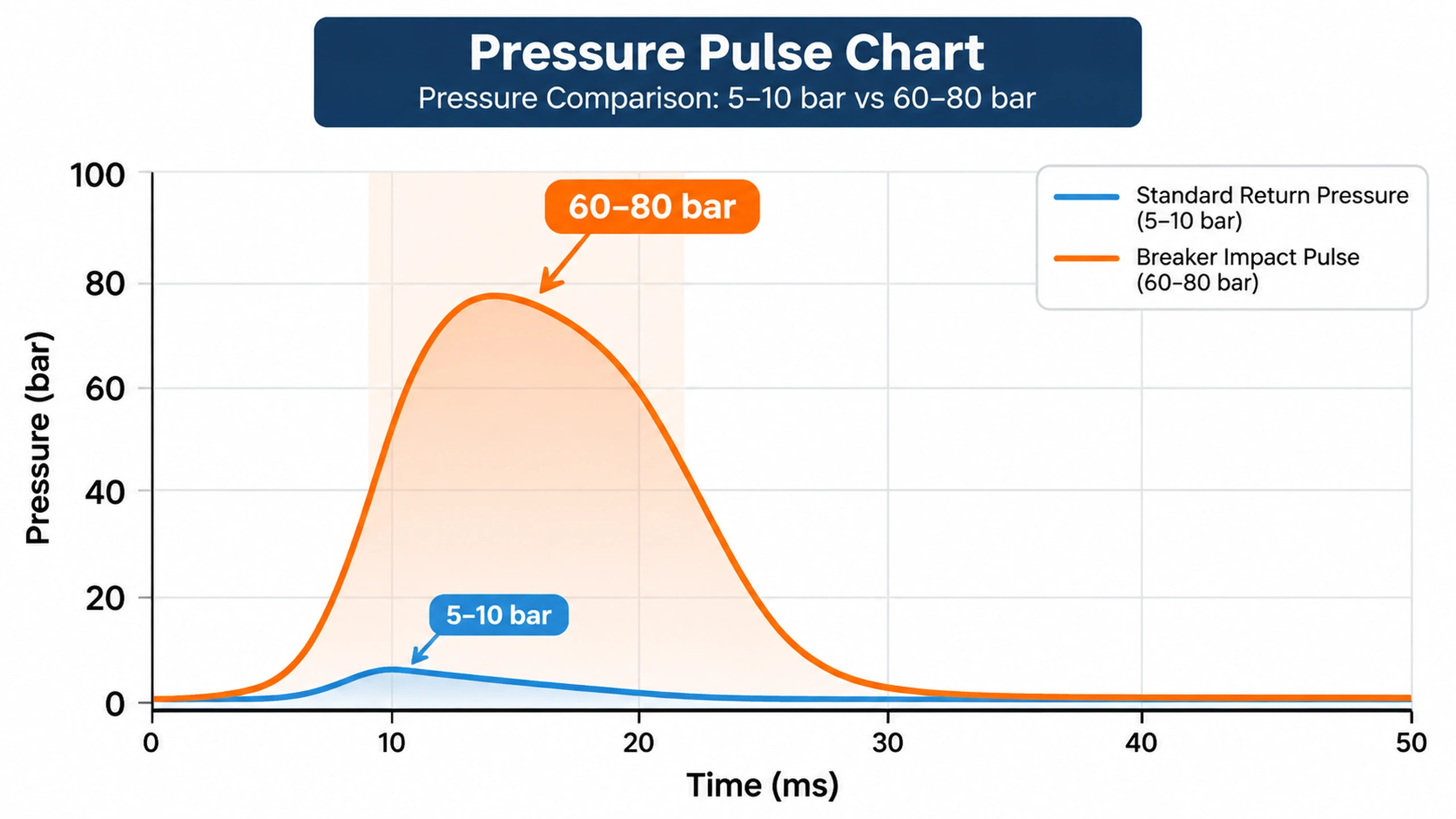
The chart below is an example of the contrast that can exist between steady return flow and breaker operation. The values must be measured on the actual machine; they are not universal pressure limits.
| Operating condition | Example pressure observation | What it means for the cooler |
|---|---|---|
| Normal return flow | about 5–10 bar in some circuits | Core sees a relatively steady differential |
| Breaker operation | repeated transient peaks far above the steady value; 60–80 bar is one observed range in the source material | Fatigue cycles increase at braze fillets and joints |
| Restricted return or failed accumulator | higher and sharper peaks | The cooler may be exposed to a pressure wave beyond its qualification |
The source statement that a breaker produces 60–80 bar (870–1,160 psi) pulses may describe a severe installation. Do not use it as a universal acceptance limit. A smaller breaker, a dedicated return, a correctly charged accumulator or a different cooler location can produce a very different waveform.
Inspect the circuit before the cooler
Check the following components in order:
- Breaker return requirement: confirm the maximum allowable return backpressure and whether the cooler may be installed in that line.
- Return hose and fittings: look for undersized hose, sharp bends, reducers, quick couplers and long vertical runs.
- Return filter: confirm the element is correct and not restricted.
- Accumulator: verify precharge, bladder or piston condition and connection to the return line.
- Backpressure valve: confirm the setting and flow capacity.
- Cooler location: verify that it is not exposed to pressure pulses from a line it was not designed to protect.
- Mounting: check for loose brackets, rigid pipe connections and hose strain.
A pressure pulse can be amplified by a closed valve, a blocked filter or a long column of oil. Replacing the cooler without correcting those conditions can simply move the failure to the next weakest point.
Fatigue qualification is not a burst-pressure claim
A pressure vessel or heat exchanger can pass a single proof or burst test and still fail under repeated lower-amplitude cycles. The relevant questions are:
- What is the pressure amplitude at the cooler?
- How many cycles occur per hour and over the service life?
- What is the mean pressure and oil temperature?
- Does the test include the actual mounting and port loads?
- Are the braze fillets and parting sheets inspected after cycling?
- Is there a pressure-pulse accumulator or dampener?
Ask the supplier for a fatigue test or a documented design basis, not only a maximum pressure number. A suitable replacement may use stronger internal joints, modified header geometry or a different core construction, but the system pulsation still has to be controlled.
For high-cycle applications, review the vacuum brazing versus CAB comparison and the bar-and-plate oil cooler assembly.
How quickly can a breaker damage a cooler?
The source material describes core rupture within 200–500 operating hours in a severe case. That is a useful warning, not a universal service life. Fatigue life depends on the pressure amplitude, number of blows, mean pressure, oil temperature, core geometry, braze quality and mounting vibration.
A cooler can fail earlier if:
- The return line is undersized or restricted
- The accumulator is discharged, damaged or incorrectly connected
- The breaker is operated outside its approved flow and backpressure range
- The cooler is subjected to pressure pulses for which it was not qualified
- The core has a weak braze fillet or header transition
- The cooler is rigidly mounted and also receives chassis vibration
Inspect the pressure waveform before estimating life. A count of operating hours alone does not define the fatigue exposure.
Prevention and retrofit checklist
| Area | Recommended action |
|---|---|
| Breaker compatibility | Confirm required flow, blow frequency and maximum return backpressure |
| Return circuit | Use the specified dedicated return path and avoid unnecessary restrictions |
| Hose and fittings | Maintain adequate diameter and smooth routing; minimize couplers and sharp bends |
| Accumulator | Verify precharge, bladder condition and proper connection |
| Filtration | Maintain the correct filter without creating excessive backpressure |
| Cooler selection | Match pressure rating, fatigue qualification and thermal duty |
| Mounting | Isolate vibration and avoid loading ports or brackets |
| Instrumentation | Log pressure peaks at the cooler during breaker operation |
| Maintenance | Inspect hoses, accumulator and cooler mounts at defined intervals |
For custom packaging, the industrial machinery cooling page and the bar-and-plate sizing guide can be used as starting points. The final design still needs the actual breaker waveform.
What to send for a cooler review
Provide:
- Excavator model and hydraulic configuration
- Breaker make, model and blow frequency
- Pump flow and relief settings
- Allowable return backpressure
- Pressure waveform at the cooler inlet and outlet
- Accumulator and backpressure-valve details
- Hose length, diameter and routing photos
- Cooler part number, drawing and failure location
- Oil type, temperature and filtration
- Operating hours before failure
A replacement should be selected for both thermal performance and pressure-fatigue duty. A larger core can improve cooling while making the pressure-pulse problem worse if its internal geometry and mounting are not reviewed.
Need help with a breaker-cooler failure?
Send the pressure log, breaker model, cooler photos and return-circuit layout. Our engineers can review whether the failure is primarily thermal, mechanical or pressure-fatigue driven before proposing a replacement or retrofit.
Frequently Asked Questions
Why do hydraulic rock breakers cause excavator oil cooler fatigue?
The breaker produces rapid flow and pressure pulsations in the return circuit. Repeated pressure cycles can fatigue brazed joints, headers and brackets even when the average return pressure appears normal. The exact amplitude and life depend on the circuit, accumulator, hose routing and cooler design.
Are 60–80 bar return-pressure pulses normal for every breaker?
No. Those values may occur in a particular installation, but breaker size, return backpressure limits, accumulator condition and plumbing change the waveform. Measure the actual pressure at the cooler inlet and compare it with the breaker and cooler specifications.
Is this failure the same as water hammer?
The mechanism can include water-hammer-like pressure transients caused by rapid flow changes, but it is more accurately described as high-frequency hydraulic pressure pulsation unless the circuit actually experiences a sudden flow reversal or valve closure.
Does a higher static burst rating prevent fatigue failure?
No. A cooler can survive a one-time burst test and still fail under millions of pressure cycles. The design must be qualified for the pressure amplitude, cycle count, temperature and mounting vibration of the breaker application.
What information is needed for a replacement cooler review?
Provide the breaker model, blow frequency, pump flow, allowable return backpressure, measured pressure waveform, accumulator and valve details, hose layout, cooler drawing and failure photos.